Surface, Alignment and Coordinate Tools
Overview
The DGDT includes four utilities for the processing and querying of 3D surfaces, alignments and tidal data.
- Set Coordinate Chainage Offset Tool: Calculates the coordinates to/from chainage and offset based on alignment data.
- Set Elevation or Depth from Surface Tool: Sets the depth or elevation for a range of table structures from 3D surfaces.
- Set Seabed Elevation Tool: Calculates seabed elevation for each point based on water depth and tidal information.
- Grid File Pre-processing Tool: Pre-processes surface files to produce perfect grids, slice up over sized grids, invert elevations and replace null values.
Set Coordinate Chainage Offset Tool
Set Coordinate Chainage Offset Tool gINT Add-In allows the user to calculate the coordinates/chainage/offset for records on the POINT table from a pre-defined alignment name, chainage, offset and coordinates, or vice versa. The alignment data is stored on the gINT native Alignment tables in the project database.
To start Set Coordinate Chainage Offset Tool:
- Select INPUT tab.
- Select Add-Ins > Datgel DGD Tool > Set Coordinate Chainage Offset.
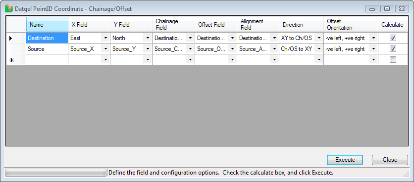
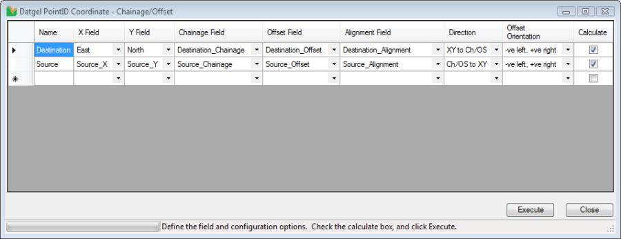
On this screen:
Name column: Name for each Set Coordinate Chainage Offset process. Ensure the name for each row is entered and not duplicated. The name is used to uniquely identify each row
X Field column: A drop down list of all the fields in the POINT table, defines the field name of the X, or East field.
Y Field column: A drop down list of all the fields in the POINT table, defines the field name of the Y, or North field.
Chainage Field column: A drop down list of all the fields in the POINT table, defines the field name of the Chainage field.
Offset Field column: A drop down list of all the fields in the POINT table, defines the field name of the Offset Field.
Alignment Field column: A drop down list of all the fields in the POINT table, defines the field name of the Alignment field.
Direction column: A drop down list with two options to calculate Chainage/Offset or East/North for each PointID on POINT table. Select "Ch/OS to XY" if you wish to calculate East and North values and select "XY to Ch/OS" if you wish to calculate Chainage and Offset values.
Offset Orientation column: A drop down list with two options to define offset orientation. Select "+ve left, -ve right" option if on the left of the chainage line is positive and select "-ve left, +ve right" option if on the left of the chainage line is negative.
Calculate column: This is used to indicate whether to calculate Coordinate Chainage Offset or not after "Calculate" button clicked.
Execute button: Start Set Coordinate Chainage Offset process for each PointID on the POINT table.
Usage
- Enter values into Name, X Field, Y Field, Chainage Field, Offset Field, Alignment Field, Direction, Offset Orientation and Calculate columns.
- Click Execute button to start the Set Coordinate Chainage Offset process.
Set Elevation or Depth from Surface Tool
The Set Elevation or Depth from Surface Tool allows the user to set an elevation or depth field of a table in gINT from values in a gINT surface based on the PointID's East and North.
Surfaces may be stored in the project file or externally in a gsf file.
To launch Set Elevation or Depth from Surface Tool:
- Select the INPUT tab.
- Select Add-Ins > Datgel DGD Tool > Set Elevation or Depth from Surface.
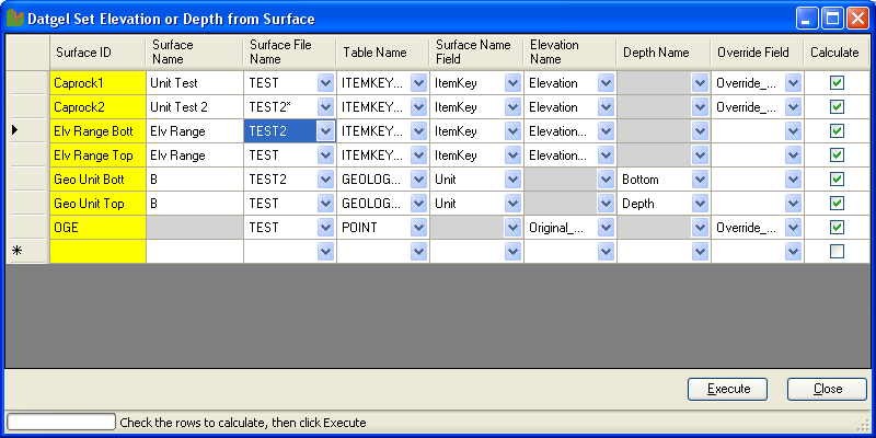
On this screen:
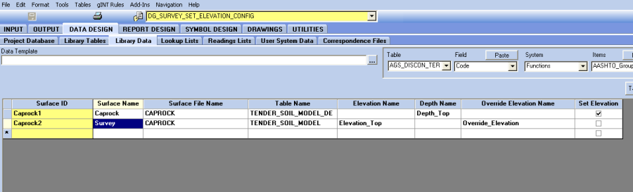
Surface ID column: Surface ID is used to uniquely identify each row. This field is coloured yellow, and similar to the yellow coloured fields in gINT, this field must have a value before executing or closing the form.
Surface Name column: The surface name used when inserting a new surface into a selected table with PointID and ItemKey as the keyset.
Surface File Name column: External or internal surface file name. You can enter the exact surface file name or use a wildcard in the surface file name. For example, if you have surface file named as S_01, S_02 and S_03, in this column you can enter "S*" to include all these surface files when defining the elevation.
Table column: A drop down list of all the PointID, PointID,Depth and PointID,ItemKey keyset tables in current gINT Project file. Certain columns are not applicable depending on the table selection. These fields will be automatically coloured grey and become un-editable when changing the table name column, or become available when an applicable table is selected.
Elevation Field column: A drop down list of all the fields from the selected table to select the field that you want to set the elevation to. This will update the elevation for all the holes on the point table that have East and North (Destination X and Y) data. If an Elevation field is specified, then the Depth field will be greyed out and become un-editable until the Elevation field value is cleared.
Depth Field column: Defines the field on the selected table where the Depth values will the written. The column has a drop down list of all the fields from the selected table. The depth is relative to the elevation of the PointID, and is calculated by subtracting the elevation of the surface file from the elevation of the PointID, which is defined on the POINT table. This will update the depth for all the PointIDs that have East and North (Destination X and Y) data. If a Depth Field is specified, then the Elevation Field will be greyed out and become un-editable until the Depth field value is cleared.
Override Field column: Defines the Boolean field on the selected table that defines if the depth or elevation has been defined manually, and hence not to be overridden by this command. A drop down list of all the fields from the selected table. Ensure the selected override elevation field is a Boolean / check box field. This field is optional.
Set column: Indicates whether to set the elevation or not. If "Set" is checked, depth or elevation will be updated after Execute button clicked.
Execute Button: Sets the surface elevation.
Usage
- Enter values into Surface ID, Surface Name, Surface File Name, Table Name, Elevation Name or Depth Name, Override Field, and Set columns.
- Click Execute button to start the process. An error log will be shown in a message window at the end of the process.
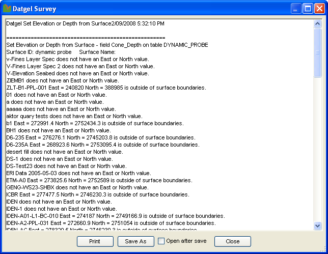
The log file displays a message for each PointID. For example, if the East and North lay outside the surface areas, then an error message will be listed. - Click Save and Close on the main form to return to gINT INPUT.
Setting Storage
The Set Surface Elevation Form is populated with data in DG_SURVEY_SET_ELEVATION_CONFIG table in the current gINT library file.
Set Seabed Elevation Tool
The Seabed Elevation Tool allows the user to calculate seabed elevation for each PointID based on water depth and tidal information. This will update all records on the POINT table that have tidal date/time and tidal water depth information.
To start Set Seabed Elevation Tool:
- Select INPUT tab.
- Select Add-Ins > Datgel DGD Tool > Set Seabed Elevation.
Tables
Explanations of the tables used in this gINT Add-In are listed below.
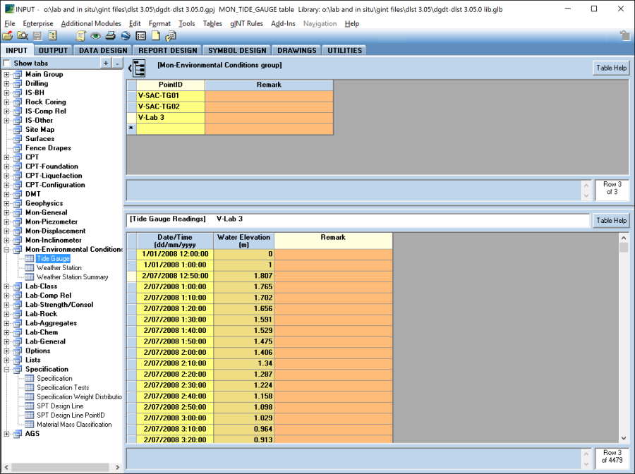
The Tide_Gauge table is in the Mon_Environmental_Conditions table. The PointID is selected in the Tide_Gauge (upper) table. In the Tide_Gauge (below) table the keyset for this table is PointID,DateTime.
The Water_Elevation field will be used when calculating the Elevation on the POINT table.
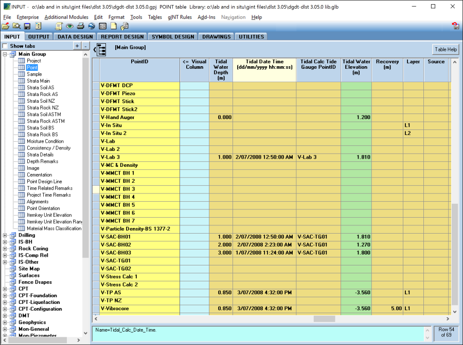
The following fields on the POINT table are used by this tool:
- Tidal Water Depth: Stores each PointID's Tidal_Water_Depth information.
- Tidal Date Time: Stores each PointID's Tidal_Date_Time information. This field is used by the Tool to get each PointID's Tidal_Water_Elevation from the Tide_Gauge table.
- Tidal Calculation Tide Point Gauge: Stores each PointID's information. This field is used by the Tool to get each PointID's Tidal_Water_Elevation from the Tide_Gauge table
- Tidal Water Elevation: This field is used to store the calculated tidal water elevation which is populated from Tide_Gauge table based on each PointID's Tidal_Calc_Tide_Gauge_PointID and Tidal_Date_Time information.
- Elevation: This field is used to store the calculated seabed elevation for each PointID.
Usage
The Elevation field on the POINT table is calculated using the add-in menu command Add-Ins > Datgel DGD Tool > Set Seabed Elevation. This will update all records on the POINT table that have Tidal_Date_Time, Tidal_Calc_Tide_Gauge_PointID, Tidal_Water_Depth information and corresponding Tidal data on the Tide_ Gauge table. The user needs to manually enter each PointID's Tidal_Water_Depth and Tidal_Date Time information. Tidal_Water_Elevation field in POINT table will be updated from Tide_Gauge table based on each PointID's Tidal_Date_Time information. Each PointID's Elevation is calculated using the difference between each PointID's Tidal_Water_Elevation and Tidal_Water_Depth values.
Grid File Pre-processing Tool
The Grid File Pre-Processing Tool allows the user to:
- Pre-process a grid surface file to fill in the null regions to form a perfect rectangular outline with no holes
- Divide the source grid file into several smaller rectangular grid files to cope with larger surface files
- Invert data, i.e. multiply Z by -1
To launch Grid File Pre-processing Tool gINT Add-In:
- Be in gINT INPUT.
- Select Add-Ins > Datgel DGD Tool > Surface File Pre Process.
On this screen:
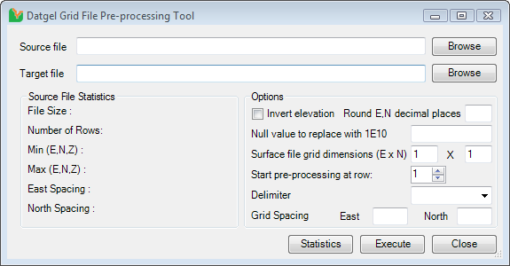
Source file: The file path of the source XYZ grid file to be processed. Use the "Browse" button to browse to the file.
Target file: The file path where the output XYZ grid file(s) will be generated. Use "Browse" button to select browse to the file path.
File size: Displays the source file is in bytes and Megabytes.
Number of rows: Shows the number of rows in the source file.
Min (E, N, Z): Shows the minimum East, North and Elevation values from the source file.
Max (E, N, Z): This information shows the maximum East, North and Elevation values from the source file.
East spacing: This information shows the East spacing between each row record in the source file. Ensure the east value of the row records in the surface file are equally spaced before you start the grid file pre-processing process.
North spacing: This information shows the North spacing between each row in the source file. Please make sure the north value of the row records in the surface file are equally spaced before you start the grid file pre-processing process.
Statistics Button: Use this button to display source file statistics. This is not required but it is useful to know the file statistics in order to decide how the target files are divided. Note that the source file statistics will be calculated and be shown in the Statistics section at the end of the pre-processing process.
Invert elevation checkbox: Check the "Invert elevation" box to invert elevation in the target grid file, i.e. multiple the elevation by -1. This is required only if the elevation in the source gird file has the elevation inverted and this needs to be corrected before import into gINT.
Round E,N decimal places: Specify a value here to round all values to a number of decimal places. Rounding can correct inconsistent grid spacing if the difference is very small. Leave this blank if you wish to omit any rounding.
Null value to replace with 1E10: gINT recognised values greater than or equal to 1E10 to be Null values. If the source grid file uses a different value to represent a Null, then enter that value in the text box and the Tool will replace the value with 1E10
Surface file grid dimensions (E x N): Enter the East Grid dimension and North Grid dimension to cut the grid files into equally spaced portions. You can use "File Size" information to determine the East and North Grid dimensions. For example, if the surface file grid dimension is 2 x 2, the source surface file will be cut into two rows and two columns, resulting into 4 files and will be named as <Target File Name>_GridX1_GridY1.xyz, <Target File Name>_GridX1_GridY2.xyz, <Target File Name>_GridX2_GridY1.xyz and <Target File Name>_GridX2_GridY2.xyz.
Start pre-processing at row: You can specify the starting row in the source file for the process. This is useful if the source surface file has header information. If the actual surface record starts at row 5 in the surface file, then enter "5" in this box.
Execute button: Pre-process the source grid file.
Delimiter: The character used to separate the X, Y and Z values. The most common types can be selected from the pick list provided, or type in the delimiter character in this field.
Grid Spacing: the spacing between one coordinate to an adjacent coordinate in the grid file. If the grid spacing is known, enter the values in both East and North fields, and the Tool will use these values when pre-processing. If one or both fields are left blank, then the Tool will automatically determine the grid spacing.
Usage
- Select source grid file.
- Select target grid file.
- Click Statistics button to display source grid file statistics.
- Check Invert Elevation option if the source xyz file has the elevation inverted. Otherwise uncheck it.
- Enter a new null value to replace the default null value.
- Enter surface file grid dimensions. You can determine the dimensions by looking at the size of the source file.
- Enter the pre-process starting row in the source file. If there is no header information in the source file, then enter 1 as the starting row.
- Select a delimiter from the pick list, or enter one in the field.
- Enter the grid spacing for East and North, if known.
- Click Execute button to pre-process the source file.
- You can view the generated target files in the target file directory.