General Project Tables
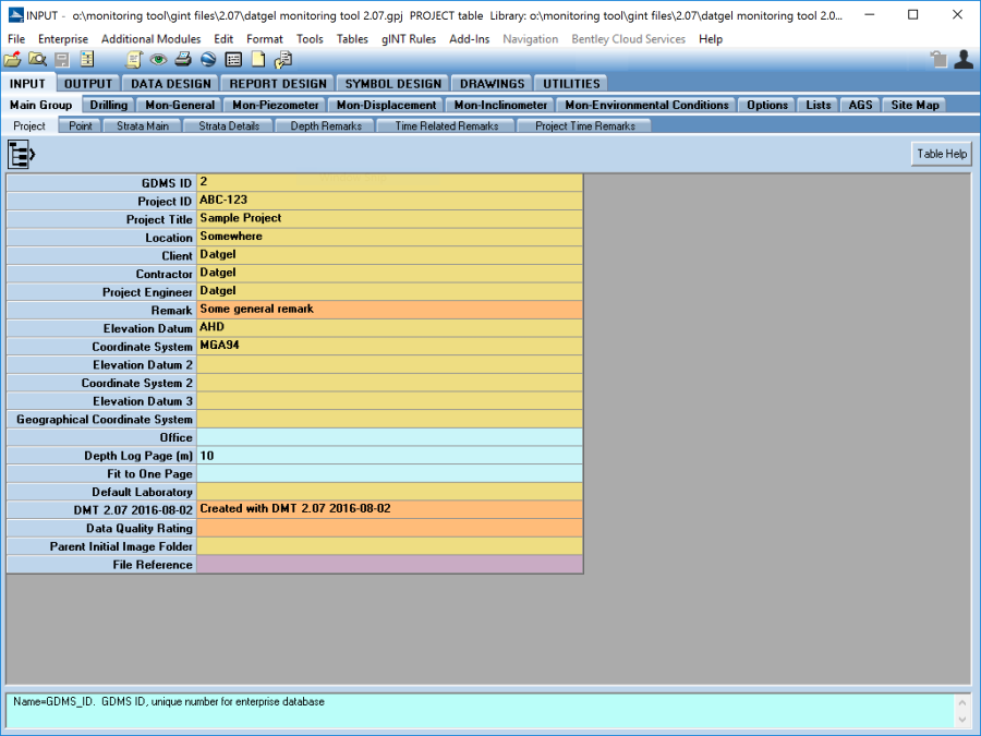
Project
The general project information, such as the Project_ID and Project_Name, should be recorded on the Project table.
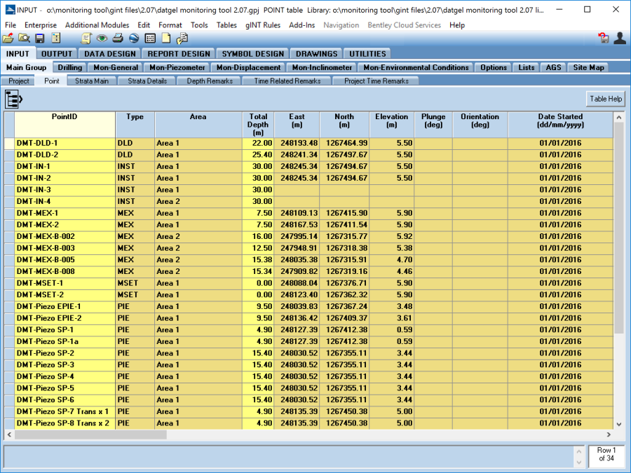
Point
At a minimum, the Point, Total_Depth, and Surface_Completion of the hole should be recorded on the Point table. In addition, the Type, East, North, Elevation, Plunge and Orientation data should also be recorded and the Depth_Log_Page value should be specified. You may wish to complete the remaining metadata fields for completeness.
The Show_Surface_Completion allows the user to show the surface completion (check the box) or not (uncheck the box). This option applies on reports MON INCL INSTALLATION LOG and MON PIEZOMETER INSTALLATION LOG. The type of Surface Completion is stored in the field Surface_Completion on Point table.
Backfill
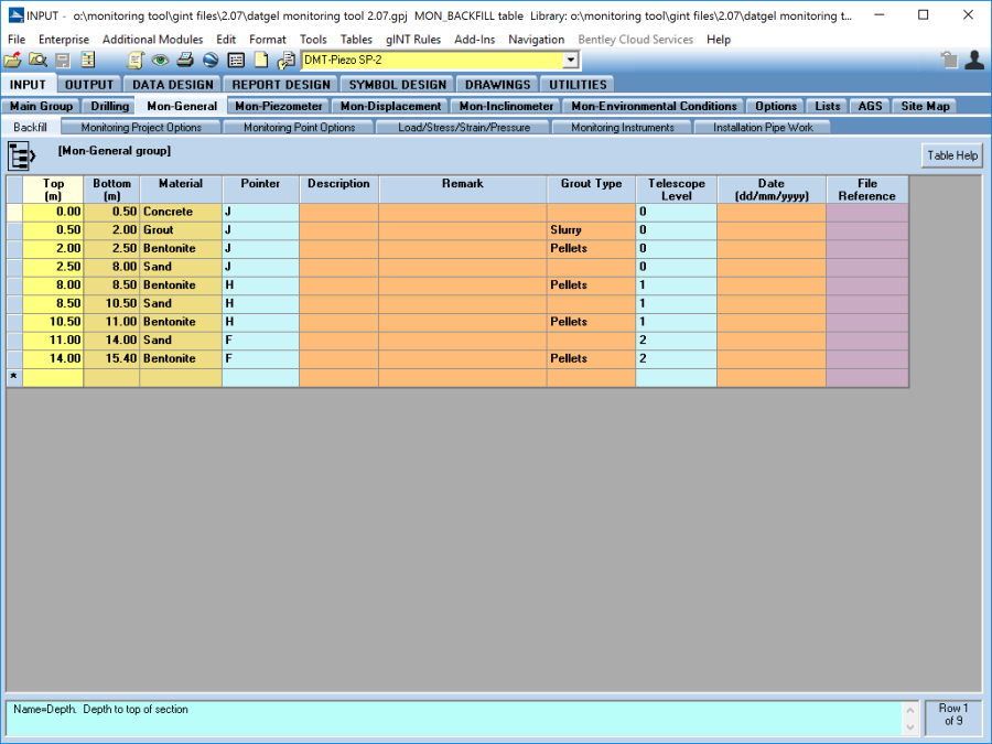
The Backfill table is used to store the installation backfill material details and other associated data for Piezometer, Deep Datum and Magnetic Extensometer installations.
Enter the Top and Bottom depths for each backfill Material type. Where there are multiple piezometer installations within a single hole, each zone (Top and Bottom Depths) of backfill material needs to be defined in the backfill table.
Should the diameter of the hole reduce with depth, the Telescope_Level field can be used to represent this. For each reduction in the diameter the Telescope_Level should be increased. For example, the default Telescope_Level is 0 and would be used to represent the initial diameter of the hole. If the diameter of the hole is reduced during the course of drilling, this could be represented in the backfill by selecting a Telescope_Level of 1 where the Top depth equals the depth at which the reduction in the hole diameter occurs. Each subsequent reduction in the diameter of the hole can be represented by increasing the Telescope_Level to a maximum of 4.
To add a pointer from the Backfill material to the installation, select an applicable pointer type that coincides with the telescope level at that depth. For example, if you wanted to show a pointer to the edge of the Telescope_Level 1, you would select Pointer H and if you wanted to show a pointer to the edge of the Telescope_Level 2, you would select Pointer F. If a Pointer is not selected then the Backfill material type will not be displayed.
For Piezometer - to correctly display the installation on the provided log reports, the values entered in the Top and Bottom fields on the Backfill table should correspond with the Depth_Top_Response_Zone and Depth_Bottom_Response_Zone fields on the Piezometer_Screens table
Monitoring Project Options
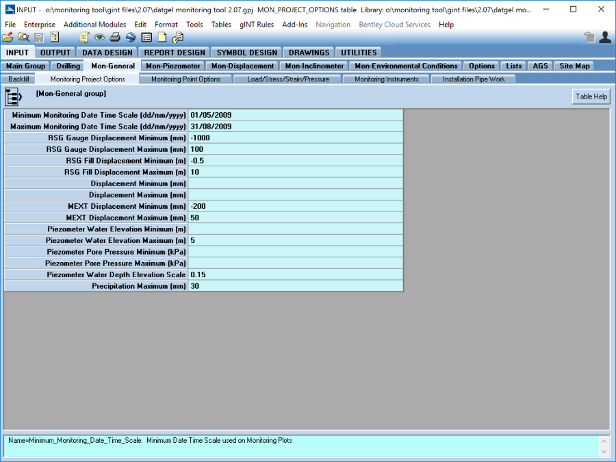
The Monitoring_Project_Options table is used to configure the output conditions for the monitoring reports. The options specified in this table are overridden by a correspondingly defined value in the relevant monitoring table or on the Monitoring_Point_Options table.
Date Time Scale
The Minimum_Monitoring_Date_Time_Scale and Maximum_Monitoring_Date_Time_Scale fields are used on the provided monitoring reports to set the minimum and maximum date-time axis extent. If they are not defined then the minimum and maximum reading values are used to define the date-time axis extent on the reports. The values entered into these fields can be overridden for an individual PointID by specifying a value on the Monitoring_Point_Options table.
Rod Settlement Gauge Options
The RSG_Gauge_Displacement_Minimum and RSG_Gauge_Displacement_Maximum fields are used to determine the minimum and maximum displacement axis values for the rod settlement gauge monitoring reports. The values entered into these fields can be overridden for an individual PointID by specifying a value on the Rod_Settlement Gauge_table.
If a minimum and maximum value is not specified in the RSG_Gauge_Displacement_Minimum and RSG_Gauge_Displacement_Maximum fields on the Monitoring_Project_Options table or in the respective fields on the Rod_Settlement_Gauge table, then the minimum and maximum reading values recorded in the Rod_Settlement_Gauge_Readings table are used to define the gauge displacement axis extents on the reports.
The RSG_Fill_Displacement_Minimum and RSG_Fill_Displacement_Maximum fields are used to determine the minimum and maximum displacement axis values for the fill materials surrounding the rod settlement gauge on the monitoring reports. The values entered into these fields can be overridden for an individual PointID by specifying a value on the Rod_Settlement_Gauge table.
If a minimum and maximum value is not specified in the RSG_Fill_Displacement_Minimum and RSG_Fill_Displacement_Maximum fields on the Monitoring_Project_Options table nor in the respective fields on the Rod_Settlement_Gauge table, then the minimum and maximum reading values recorded in the Rod_Settlement_Gauge_Readings table are used to define the fill displacement axis extents on the reports.
Displacement Options
The Displacement_Minimum and Displacement_Maximum fields are used to determine the minimum and maximum settlement axis values for deep datum and settlement marker monitoring reports. The values entered into these fields can be overridden for an individual PointID by specifying a value on the Displacement table.
If a minimum and maximum value is not specified in the Displacement_Minimum and Displacement_Maximum fields on the Monitoring_Project_Options table nor in the respective fields on the Displacement table, then the minimum and maximum reading values recorded in Displacement_Readings table are used to define the settlement axis extents on the reports.
Magnetic Extensometer Options
The MEXT_Displacement_Minimum and MEXT_Displacement_Maximum fields are used to determine the minimum and maximum settlement axis values for magnetic extensometer monitoring reports. The values entered into these fields can be overridden for an individual PointID by specifying a value on the Magnetic_Extensometer table.
If a minimum and maximum value is not specified in MEXT_Displacement_Minimum and MEXT_Displacement_Maximum fields on the Monitoring_Project_Options table nor in the respective fields on the Magnetic_Extensometer table, then the minimum and maximum reading values recorded in Magnetic_Extensometer_Readings table are used to define the settlement axis extents on the reports.
Piezometer Options
The Piezometer_Water_Elevation_Minimum and Piezometer_Water_Elevation_Maximum fields are used to determine the minimum and maximum water level axis values for groundwater monitoring reports. The values entered into these fields can be overridden for an individual PointID by specifying values on the Monitoring_Point_Options table.
If a minimum and maximum value is not specified in Piezometer_Water_Elevation_Minimum and Piezometer_Water_Elevation_Maximum fields on the Monitoring_Project_Options table nor in the respective fields on the Monitoring Point Options table, then the minimum and maximum reading values recorded in Piezometer_Readings table are used to define the water level axis extents on the reports.
The Piezometer_Pore_Pressure_Minimum and Piezometer_Pore_Pressure_Maximum fields are used to determine the minimum and maximum pore pressure axis values for groundwater monitoring reports. The values entered into these fields can be overridden for an individual PointID by specifying values on the Monitoring_Point_Options table.
If a minimum and maximum value is not specified in Piezometer_Pore_Pressure_Minimum and Piezometer_Pore_Pressure_Maximum fields on the Monitoring_Project_Options table nor in the respective fields on the Monitoring_Point_Options table, then the minimum and maximum reading values recorded in Piezometer_Readings table are used to define the pore pressure axis extents on the reports.
The Piezometer_Water_Depth_Elevation_Scale field is used to determine the water depth elevation scale on the monitoring reports.
Precipitation
The Precipitation Maximum field is used to determine the maximum value for the precipitation scale on reports.
Monitoring Point Options
Date Time Scale
The Minimum_Monitoring_Date_Time_Scale and Maximum_Monitoring_Date_Time_Scale fields are used on the provided monitoring reports to set the minimum and maximum date-time axis extent for individual PointID. The values entered into these fields will override any values that may be specified on the Monitoring_Project_Options table.
If a minimum and maximum value is not specified in Minimum_Monitoring_Date_Time_Scale and Maximum_Monitoring_Date_Time_Scale fields on the Monitoring_Point_Options table nor in the respective fields on the Monitoring_Project_Options table, then the minimum and maximum reading values recorded are used to define the date-time axis extents on the reports.
Piezometer Options
The Piezometer_Water_Elevation_Minimum and Piezometer_Water_Elevation_Maximum fields are used to determine the minimum and maximum water level axis values groundwater monitoring reports for individual PointID. The values entered into these fields will override any values that may be specified on the Monitoring_Project_Options table.
If a minimum and maximum value is not specified in Piezometer_Water_Elevation_Minimum and Piezometer_Water_Elevation_Maximum fields on the Monitoring_Point_Options table nor in the respective fields on the Monitoring_Project_Options table, then the minimum and maximum reading values recorded in Piezometer_Readings table are used to define the water level axis extents on the reports.
The Piezometer_Pore Pressure_Minimum and Piezometer_Pore_Pressure_Maximum fields are used to determine the minimum and maximum pore pressure axis values groundwater monitoring reports for individual PointID. The values entered into these fields will override any values that may be specified on the Monitoring_Project_Options table.
If a minimum and maximum value is not specified in Piezometer_Pore_Pressure_Minimum and Piezometer_Pore_Pressure_Maximum fields on the Monitoring_Point_Options table nor in the respective fields on the Monitoring_Project_Options table, then the minimum and maximum reading values recorded in Piezometer_Readings table are used to define the pore pressure axis extents on the reports.
On this page:


