Design Line
Overview
The Design Line feature allows you to define a depth or elevation related lines for material properties. The lines can be displayed on depth and elevation related graph reports. Further, multiple collections of lines maybe stored. This feature is present in both the DGD Tool and CPT Tool.
Input
The Analysis | DESIGN_LINE and Analysis | DESIGN_LINE_DATA tables define the design line for all parameters stored in the database.
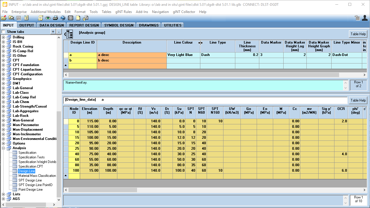
First enter a Design Line ID in the DESIGN_LINE table (upper screen), and define other fields for description and symbology.
Then click on the DESIGN_LINE_DATA table (lower screen). Each row represents a node (point or vertex) in the Design Line, where the Elevation or Depth represents the vertical axis and the Parameter (e.g. qc or qt) represents the horizontal axis. The Node ID determines the order in which the nodes are drawn, as the Design Line is constructed by drawing a line from one node to the next.
When there is a calculation using Design Line data (in the CPT Tool), the Elevation value will always take precedence over Depth when calculating the Design Line. If there are both Elevation and Depth values in this table, then only the Elevation values are used, and the Depth values are ignored. Only if the entire Elevation column is left blank, the Depth values are used.
Output
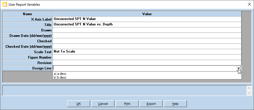
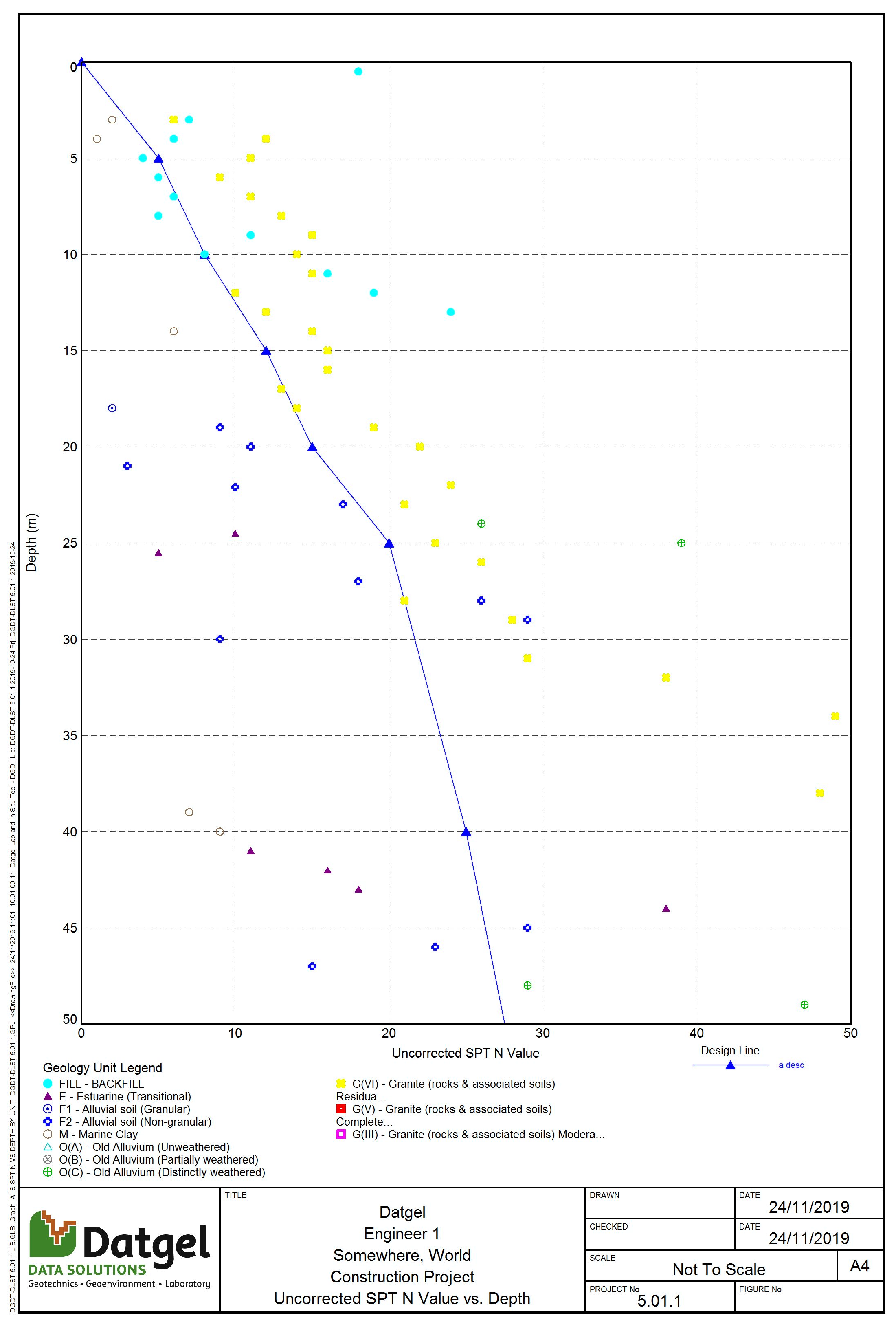
Once the Design Lines have been defined, you can show the design line on Graph reports by selecting the desired design line from the User Report Variables form.