Specification
Introduction
The specification feature allows for a user defined set of criteria to be configured on tables Specification and Specification_CPT using SQL language. The calculation is initiated by selecting Add-Ins > Datgel CPT Tool > Specification, and calculated against each PointID. The pass or fail for each criteria and over all result is written to a tables CPT_Point_Specification and CPT_Point_Specification_Detail. The results can be displayed on log reports.
The system is very flexible, it could be based on any column on a CPT_DATA_* table, or actually any PointID related table in the database. Often it would be based on a Design_Line field, which could be prepopulated from data in Design Line Data, or using a Formula Tool formula. The formula tool formula overwrites data from the Design Line Data.
In SQL statements use then place holder <<PointID>> for PointID.
Configuration
This section describes a practical example.
Formula Tool formulas
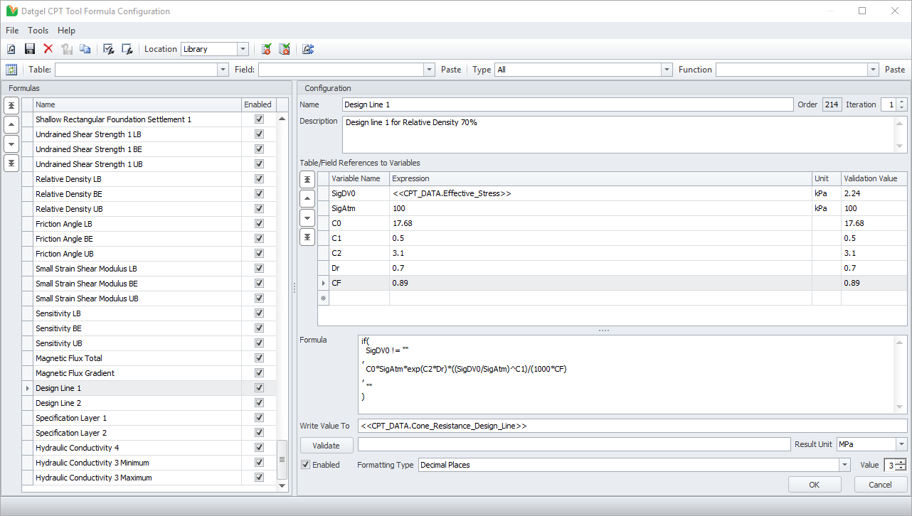
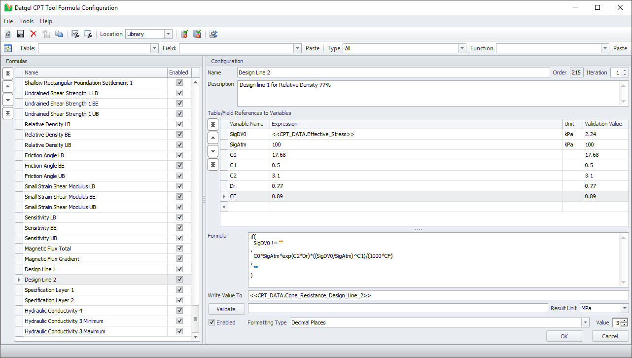
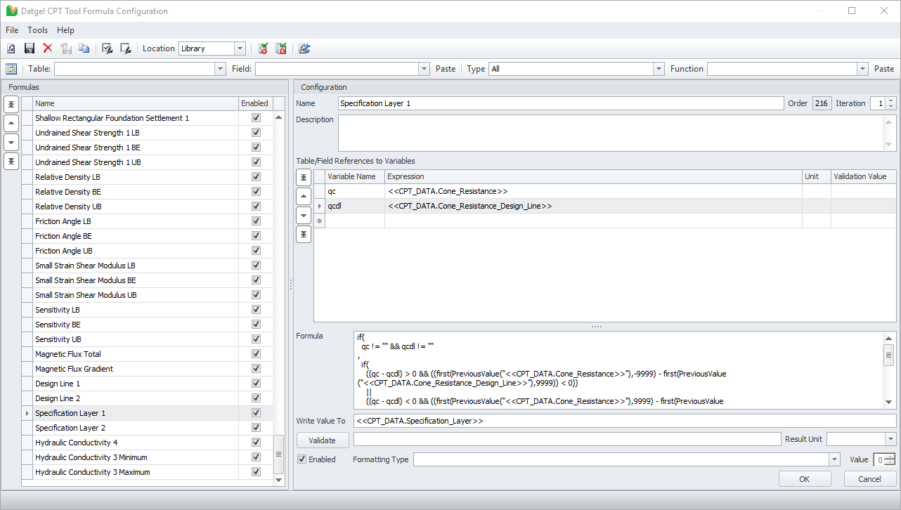
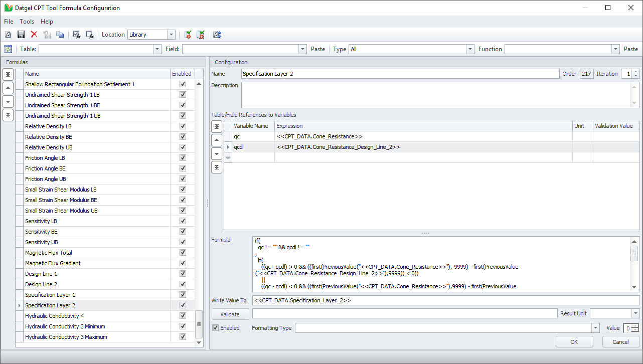
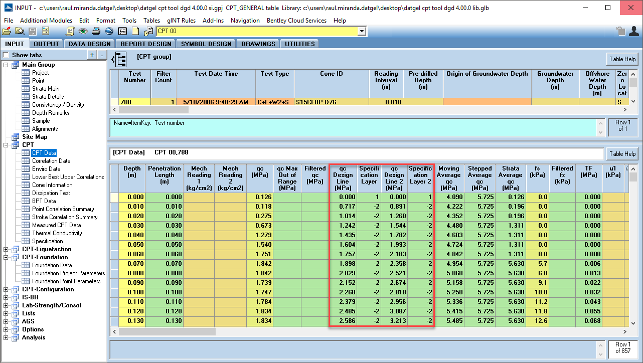
We created formula tool formulas to populate the qc_Design_Line_1 and qc_Design_Line_2, and Specification_Layer fields.
Configure Specification
To create a new specification material populate the field Specification_Material in the Specification upper table. Then populate the Description, Report_Name, Data_Marker, Colour and Remark fields too according the requirements. The following image shows the values used for this example.
In this example the qc_Design_Line_1 will be calculated as the 70% of the Relative Density, and the qc_Design_Line_2 will be calculated as the 77% of the Relative Density. The formula of the Design Line is stored in the Formula Tool.
Once a new Specification has been created, at least one Specification Detail must be created. In the lower table, assign a Detail_Name. The Detail_Name will be written to the required tables and in the report legend.
The first Specification Detail is: from 0 to 4 m depth, the qc value should be >= 70% of the Relative Density.
The Expression is:
select iif(avg([Cone_Resistance] - [Cone_Resistance_Design_Line]) >= 0,'P','F') from [CPT_DATA] where [PointID] = '<<PointID>>' and [Depth] <= 4
The second Specification Detail is: for depths >4, the qc value should be >= 77% of the Relative Density.
The Expression is:
select iif(avg([Cone_Resistance] -
[Cone_Resistance_Design_Line_2]) >= 0,'P','F') from [CPT_DATA] inner join
[POINT] on [CPT_DATA].[PointID] = [POINT].[PointID] where [CPT_DATA].[PointID]
= '<<PointID>>' and [Depth] > 4 and iif(not
[POINT].[Original_Ground_Elevation] is null and not [POINT].[Elevation] is null,
[Depth] < ([POINT].[Elevation] - [POINT].[Original_Ground_Elevation]),True)
The third Specification Detail is: Check if a layer of > 0.5 m is below 70% of the Relative Density in the depth range 0 to 4 m.
The Expression is:
select iif(count(*) > 0,'F','P') from (select
[CPT_DATA].[PointID], [CPT_DATA].[Specification_Layer], min([CPT_DATA].[Depth])
as [Top], max([CPT_DATA].[Depth]) as [Bottom], format([Bottom]-[Top],'0.00') as
[Thickness] from [CPT_DATA]
where [CPT_DATA].[PointID] = '<<PointID>>' and
[CPT_DATA].[Specification_Layer] < 0 and [CPT_DATA].[Depth] <= 4
group by [CPT_DATA].[PointID],
[CPT_DATA].[Specification_Layer]
order by [CPT_DATA].[PointID], min(depth)) as [A]
where [A].[thickness] > 0.5
The last Specification Detail is: Check if a layer of > 0.5 m is below 77% Relative Density in a depth range >4 to minimum of HoleDepth and DepthToNaturalGround.
The Expression would be:
select iif(count(*) > 0,'F','P') from
(select [CPT_DATA].[PointID],
[CPT_DATA].[Specification_Layer_2], min([CPT_DATA].[Depth]) as [Top],
max([CPT_DATA].[Depth]) as [Bottom], format([Bottom]-[Top],'0.00') as
[Thickness] from [CPT_DATA]  inner join
[POINT] on [CPT_DATA].[PointID] = [POINT].[PointID] where [CPT_DATA].[PointID]
= '<<PointID>>' and [CPT_DATA].[Specification_Layer_2] < 0 and
[CPT_DATA].[Depth] > 4 and iif(not [POINT].[Original_Ground_Elevation] is
null and not [POINT].[Elevation] is null, [Depth] < ([POINT].[Elevation] -
[POINT].[Original_Ground_Elevation]),True)
group by [CPT_DATA].[PointID],
[CPT_DATA].[Specification_Layer_2] order by [CPT_DATA].[PointID], min(depth)
) as [A]
where [A].[thickness] > 0.5
The following image shows the configuration of the Specification CPT table
Assigned Specification to Project
The Specification Material should be assigned to the project before run the calculations. In the table Project Parameters table set the field Specification_Material 1 as "A" (assigned name to the specification in the field Specification_Material in Specification table). This field is a drop down list.
Calculate Specification
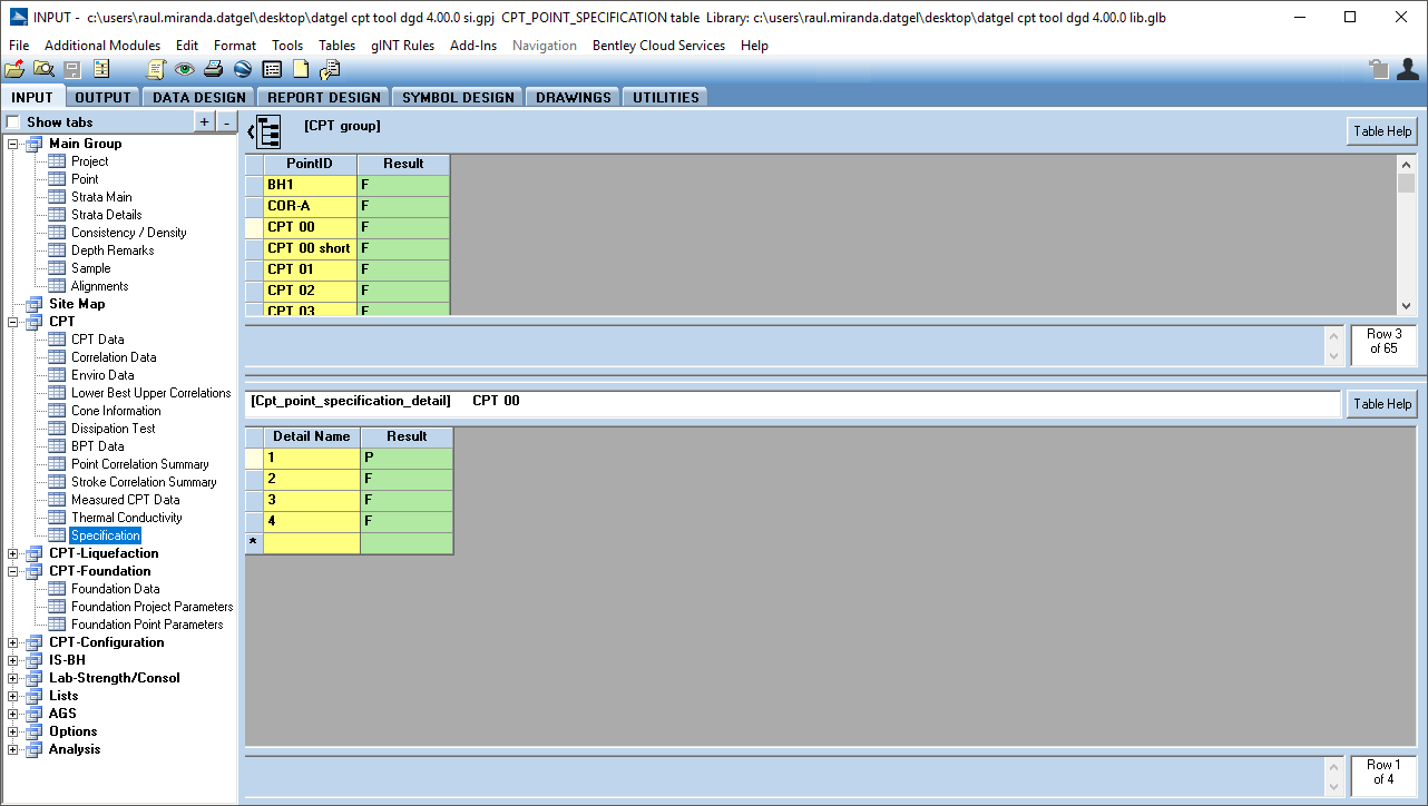
Once the Specification and the Specification Details have been entered, run the calculation by selecting Add-Ins > Datgel CPT Tool > Specification. The results of each Specification detail will be written to the table CPT_Point_Specification_Detail as "P" (Pass), "F" (Fail) or "-" (Not Applicable) according the selected expression. Only if all Specification Details are "P", the PointID will be considered "P" and it is written in CPT_Point_Specification table.
The following image shows the result for this example. In the highlighted CPT 00, the main result is Fail. The lower table CPT_Point_Specification_Detail shows the result for each Specification Detail for the CPT 00.
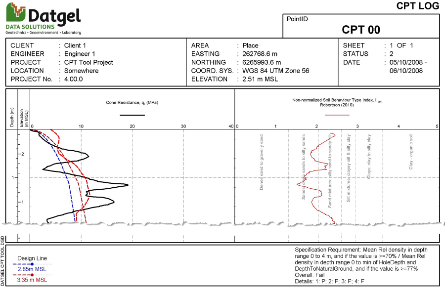
The results and design lines can be displayed on log reports.
Reports
This feature applies to all reports that contain the Design Line. On dynamic logs, turn on the design line legend in User Report Variables.
