Launching the Tool
Call the Add-in
Select Add-Ins > Datgel Output Tool > Fence Output Tool to launch the tool user interface.
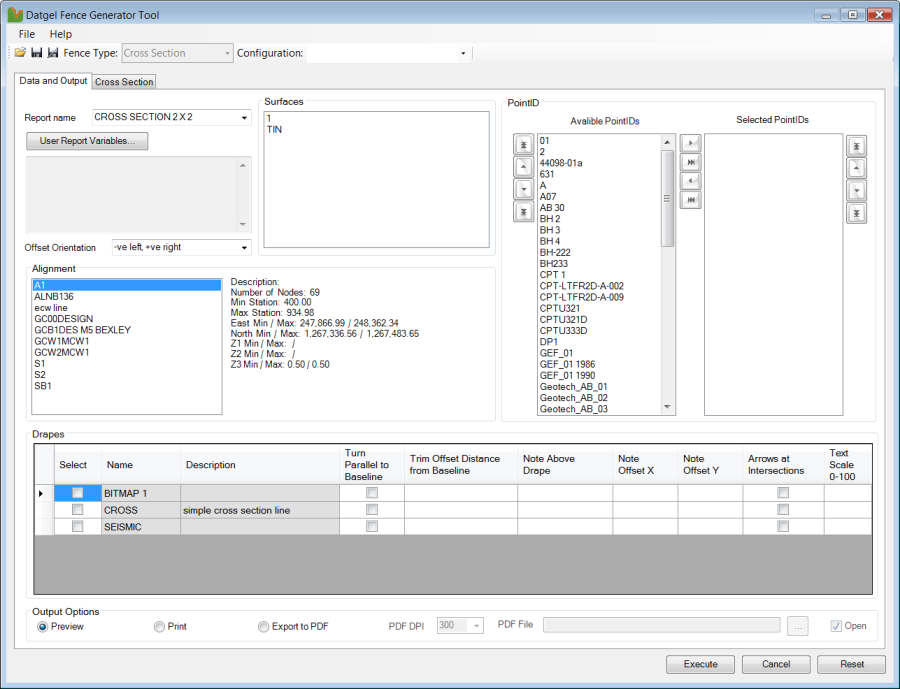
Data and Output Parameters
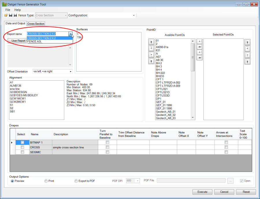
- Click on the drop down list and select the Report Name from your gINT Library that you want to display the Cross-Sections on.
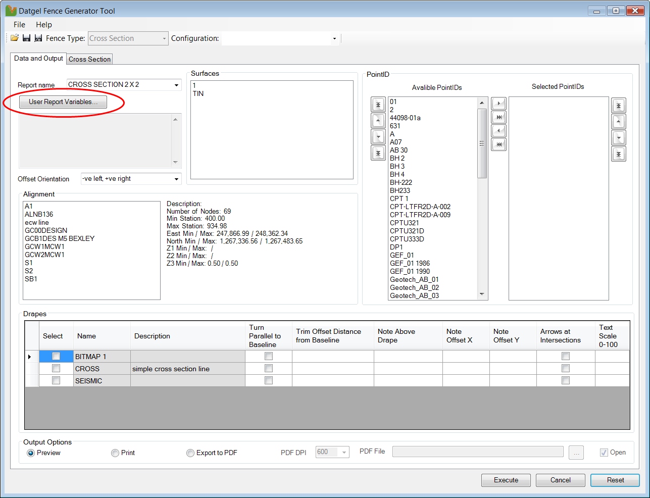
- Click on the User Report Variables.
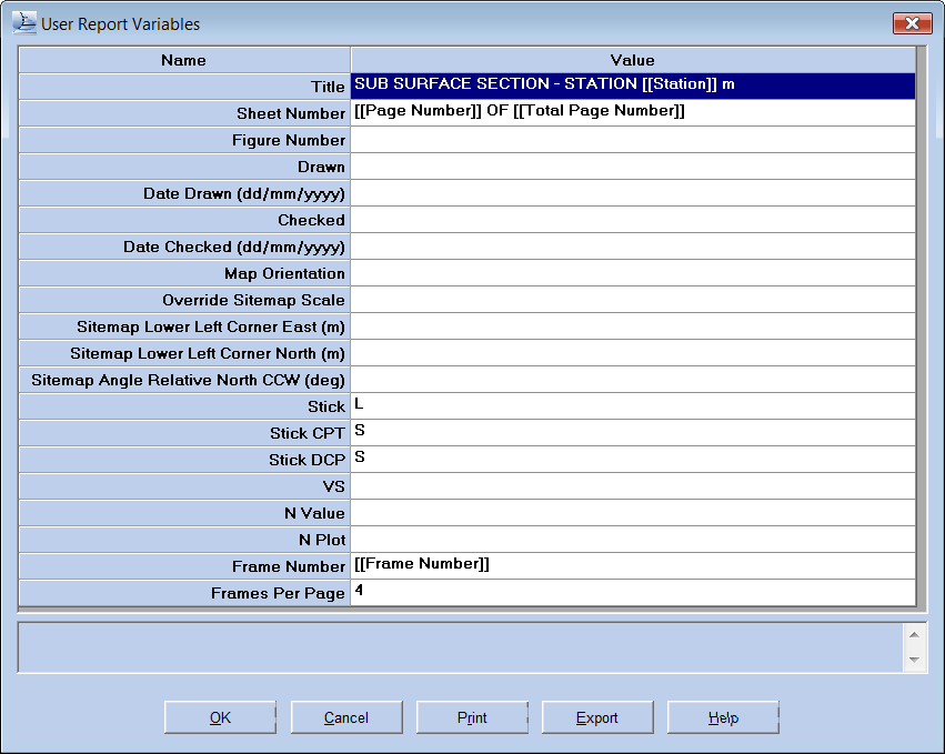
The _User Report Variables_ shown in Table 1 are referenced on the example reports. Those text surrounded by [[..].] are place holder for data_ populated by the Fence Output Tool at the time of output.
Name | Value | Notes |
|---|---|---|
Title | SUB SURFACE SECTION – STATION [[Station]] m | Station value |
Sheet Number | [[Page Number]] OF [[Total Page Number]] | Page number of current sheet in output run |
Total number of page numbers in current run | ||
Figure Number | Figure number of the report | |
Drawn | Enter person's initials / name | |
Date Drawn (dd/mm/yyyy) | Enter the date drawn as dd/mm/yyyy | |
Checked | Enter person's initials / name | |
Date Checked (dd/mm/yyyy) | Enter the date checked as dd/mm/yyyy | |
Map Orientation | B, N | Sets the orientation of the site map. B = Baseline end points (default), N = North up |
Override Sitemap Scale | 1 (for 1:1000) | Overrides the scale of the site map by the selected value. By default the site map scale is the same as the fence x axis |
Sitemap Lower Left Corner East (m) | Overrides the coordinates of the lower left hand corner of the site map to the specified coordinates. | |
Sitemap Lower Left Corner North (m) | ||
Sitemap Angle Relative North CCW (deg) | Rotates the site map counter-clockwise through the specified angle. If the coordinates of the lower left corner are specified, the rotation is centred on the lower left corner, otherwise it is centred on the centre of the site map entities | |
Stick | L | L = Legend/material graphic (default)S = Stick/line GM = Geology Map Code colour G2 = Geology Project Unit 2 colour OR = Origin colour Combinations such as "L G2" will show both graphics |
Stick CPT | S | |
Stick DCP | S | |
VS | L, R | L entered in these fields will print info on the left side on the fence posts, and R will print info on the right side, if data exists for that hole. |
N Value | L, R | |
N Plot | L, R | |
Frame Number | [[Frame Number]] | Frame Number on current page |
Frames Per Page | 4 | Number of cross sections per page |
- Once you have entered the desired text and or selected the necessary value from a drop down list, select OK. The Fence Output Tool will then store the User Report Variables in memory for use in the generation of the Cross Sections
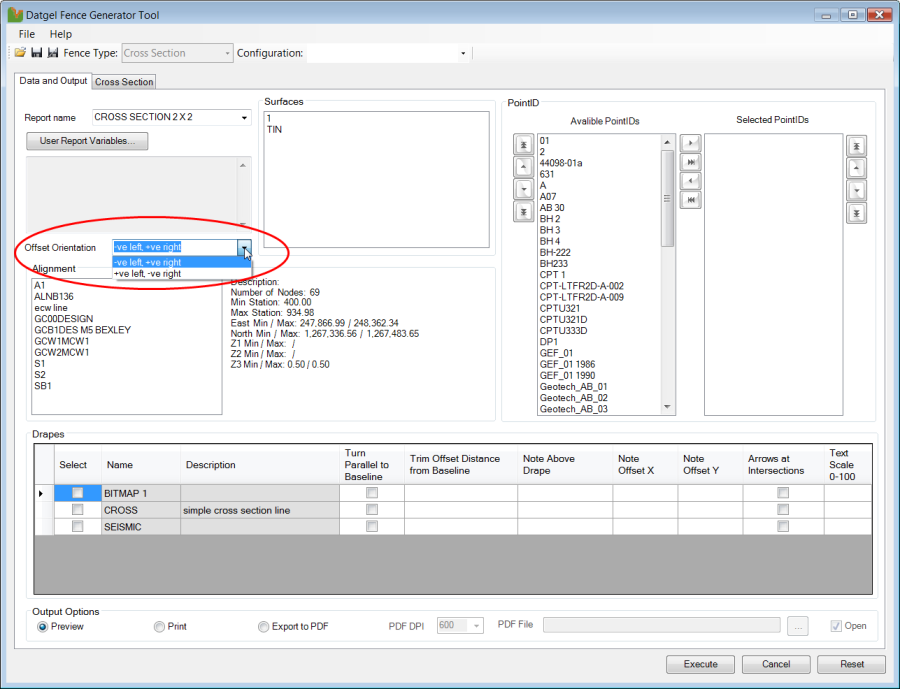
- Click on the drop down list and select the Offset Orientation that you want to use with your Cross-Sections.
- Select the Alignment, from the list, along which you want to generate your Cross Sections about.
To Select an Alignment single click on the name of the desired Alignment and to Deselect the Alignment double click on the name. These Alignments are the same as those stored in your project file.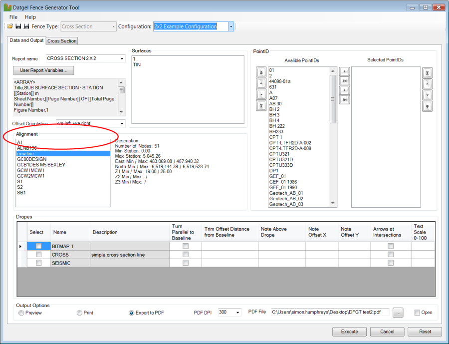
- Select the Surface, from the list, that you want to use with your Cross Sections.
To Select a Surface single click on the name of the desired Surface and to Deselect the Surface double click on the name. These Surfaces are the same as those stored in your project file. Multiple surfaces may be selected.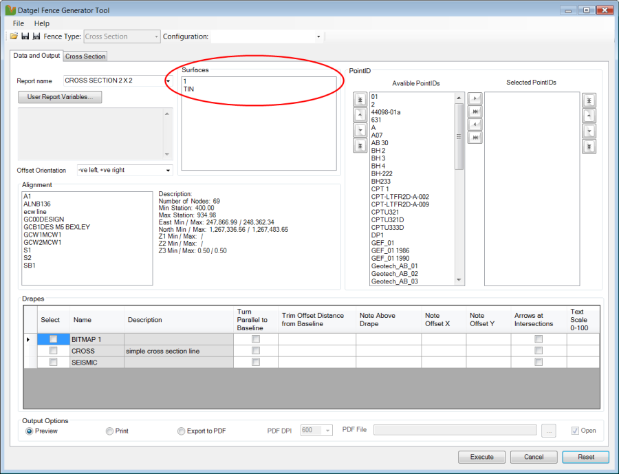
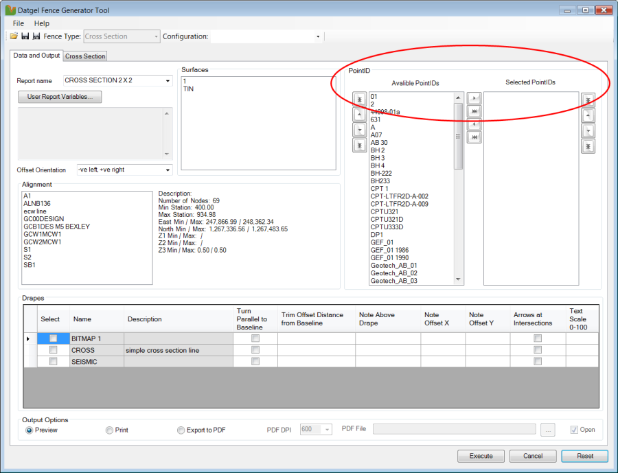
- If you wish to select individual PointIDs from the Available PointIDs list, you can do so, however it is recommended that you leave this list blank and allow the tool to determine which PointIDs are displayed by specifying the Maximum Baseline Offset on the Cross Section tab.
- Select the Drapes, from the list, that you want to use with your Cross Sections.
To Select a Drape click on the check box to the left of the desired Drape. You can also specify the Drapes settings here as you would normally do in gINT.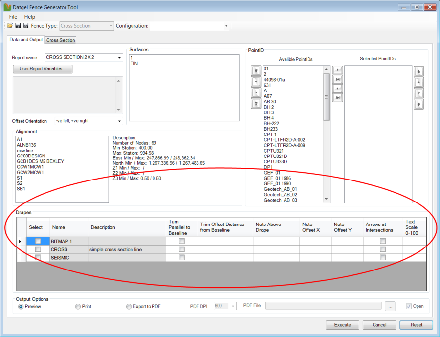
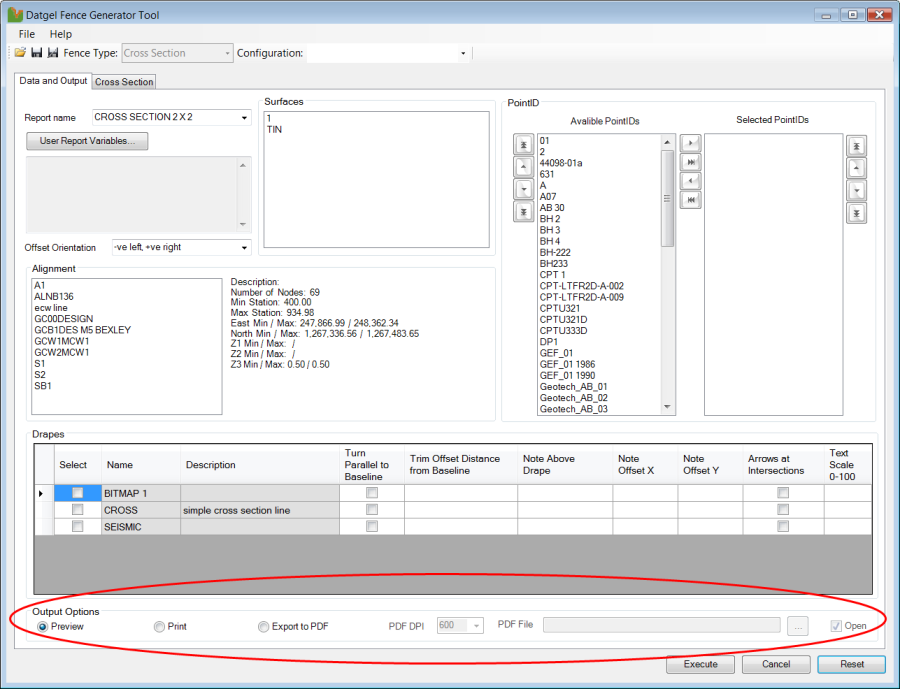
- Select the required Output Option as Preview, Print or Export to PDF.
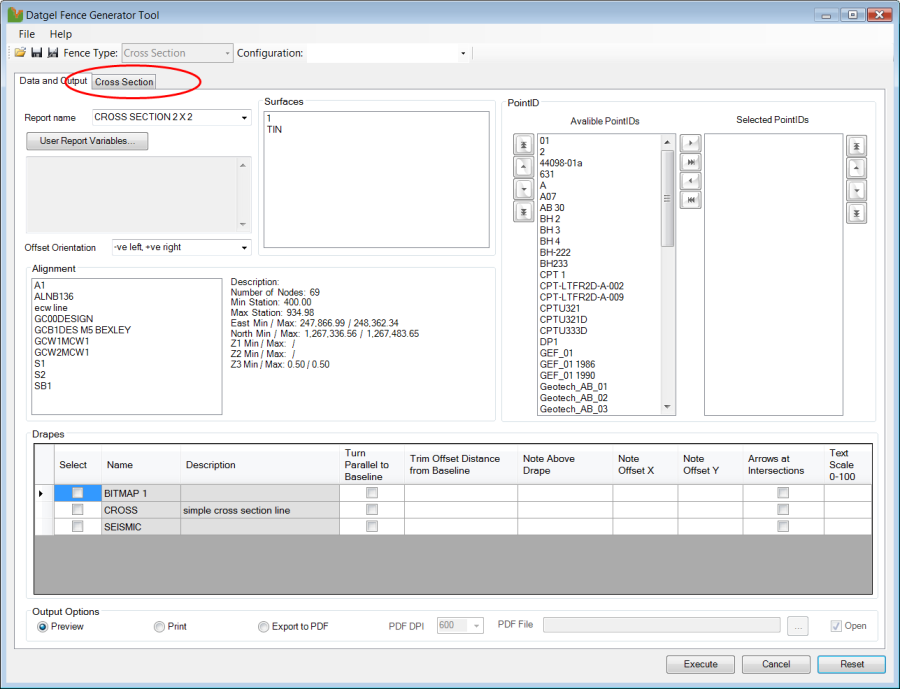
- Click on the Cross Section tab to define the necessary parameters.
Cross Section Parameters
Name | Default Value | Notes |
|---|---|---|
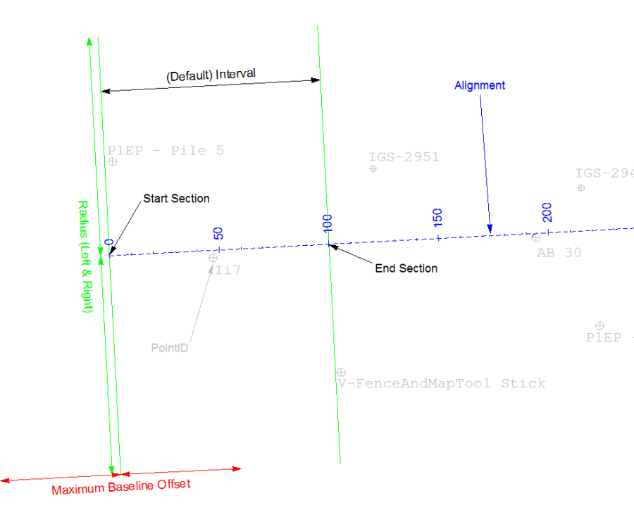
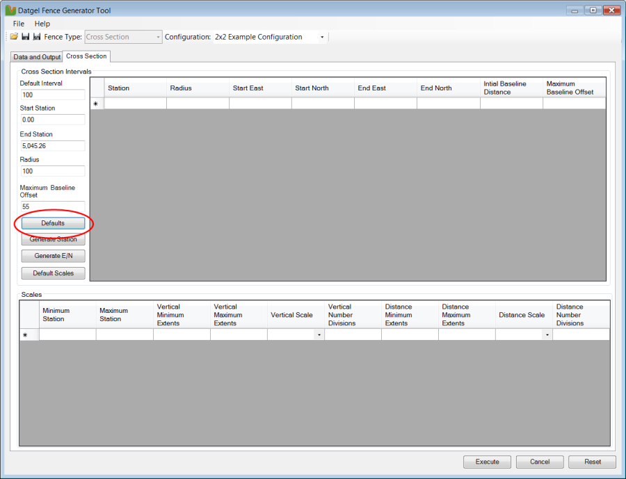
Default Interval | 100 | Space between each cross section along the alignment |
Start Station | 0.0 | Distance along the alignment where the first cross section is generated (i.e. Start Chainage) |
End Station | End point of the alignment | Distance along the alignment where the last cross section is generated (i.e. End Chainage) |
Radius | 100 | Length of the cross section line to the right and left at the Station Interval |
Maximum Baseline Offset | 55 | Specified limiting distance on each side of the cross section inside of which PointIDs will be displayed on each cross section |
Please refer to the next figure to better visualise what each of the cross section parameters refers to.
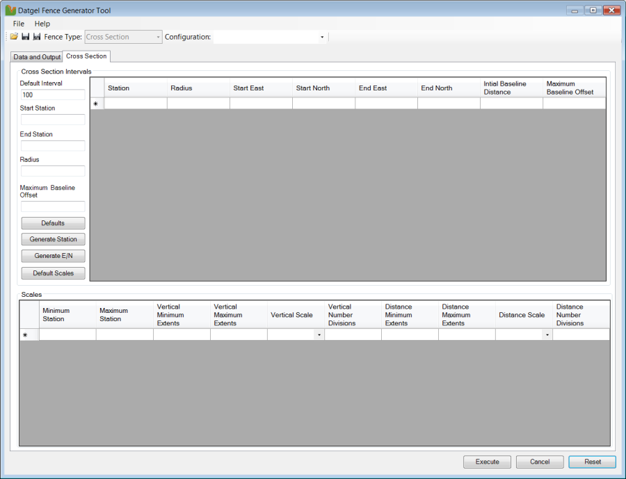
- Click on the Defaults button to populate the default Cross Section Intervals fields on the left hand side of the form. Edit the values to suit.
- Click on the Generate Station button to build the list of each cross section.
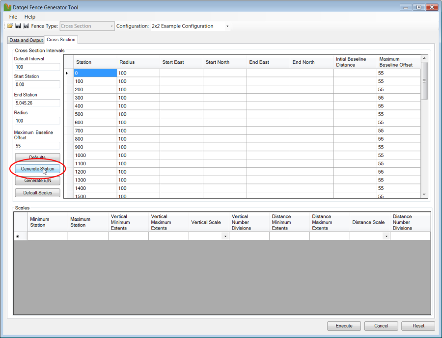
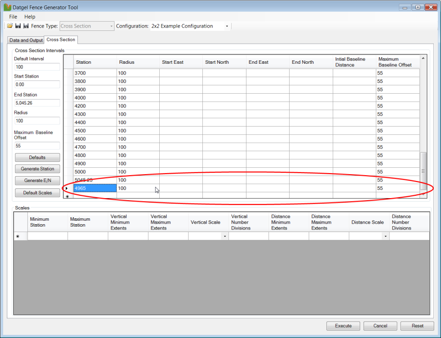
- If you do not require a cross section at every default interval you can delete them by clicking on the light grey cell located to the right of the station value that you do not require. If you wish to delete multiple stations, hold the left mouse down and drag the pointer down the list to highlight those that are not required. Alternatively, if you hold down the Control Key and left click in the grey box, you can select individual stations that you may wish to delete. Once you have selected all the records that you wish to remove, the Delete Key.
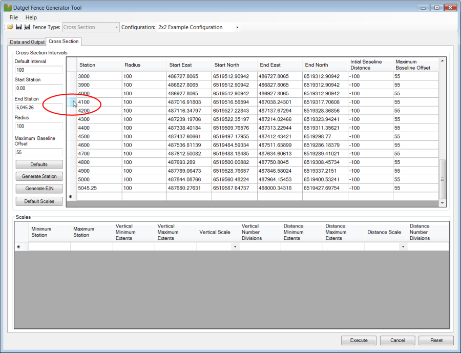
- If you wish to add additional stations, you can do so by typing in the values into empty row in the grid. You can also edit the individual details for each station should you be required to.
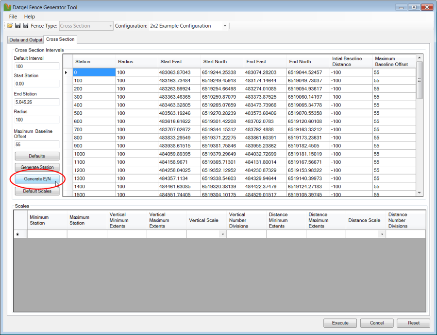
- Click on the Generate E/N button to populate the cross section list with the coordinates for the start and end of each cross section.
- Click on the Default Scales button to populate the scales list with the required values.
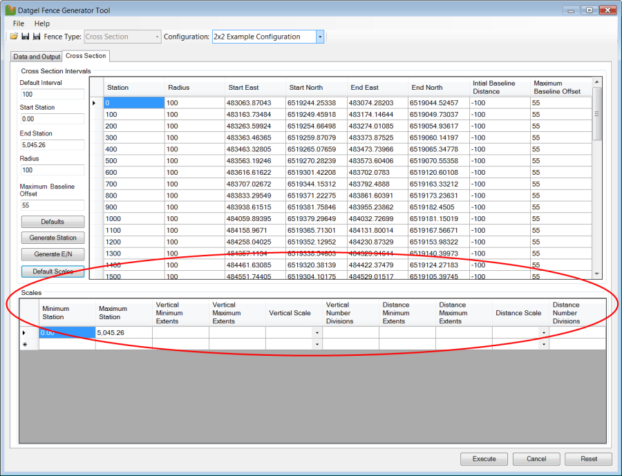
Here you can specify:
Vertical Number Divisions and -- The Vertical Minimum Extent and Vertical Maximum Extent
or - The Vertical Minimum Extent and the Vertical Scale
or - The Vertical Maximum Extent and the Vertical Scale
- The Vertical Minimum Extent and Vertical Maximum Extent
- The Distance Minimum Extent and Distance Maximum Extent
or - The Distance Minimum Extent and the Distance Scale
or - The Distance Maximum Extent and the Distance Scale
- The Distance Minimum Extent and Distance Maximum Extent