Quick Start Guide
Overview
This page guides you through the setup and explains basic use of the DGD Tool Logs Edition and Professional Edition. It uses the Australian AGS4 localization gINT files as an example, but you can follow the same process with other localizations.
gINT
gINT Logs, Professional or Professional Plus must be installed and licensed on your computer to use the DGD Tool. You need gINT Professional or Professional Plus to use the full functionality if DGD Tool Professional.
Download Datgel DGD Tool
The DGD Tool package and Datgel Toolbox Installer can be downloaded from datgel.com. Logs Edition and Professional Edition are available.
- Full version: https://www.datgel.com/customer/downloadableproducts
- Trial version: https://www.datgel.com/trial-software
Install Datgel Toolbox
Before Installation
A few basic preparations can help ensure an effortless installation.
- Make sure that the computer where you plan to install the program meets the minimum hardware and software requirements.
- Connect your PC to Internet before installation (the process may need a working Internet connection).
- The Datgel Toolbox program requires that the Microsoft .NET 4.8 framework is installed on the PC prior to the installation of the Tool. If your PC does not have this, then it will be automatically downloaded and installed during the Tool installation process.
- Log into the PC with Administrator privileges before starting installation.
- It is recommended that you exit out of other applications that maybe running on your PC.
- Close gINT before you start installation.
Installation
- Run the installer, typically named Datgel.Toolbox.20##.#.#_YYYY-MM-DDTHHmmss.exe.
- When you come to the Components screen, be sure to select this product, or you can simply install all Components.
- The gINT*.exe.config files for gINT versions V8i and 10..# are edited by Datgel software during installation.
Datgel Licensing
Product Package Content
The Download .zip contains all you need to install and evaluate the Datgel DGD Tool. The content is:
- Documentation folder:
- Example reports
- EULA
- Links to the product and licensing online user guides
- Link to email to support.
- gINT Files folder:
- gINT Project, gINT Library and gINT Data Template files customised by location. You must use the Project and library from the same location. For example (set of gINT Files for Australia):
- "dgdt-p as au ags 4.1 au si #.##.#.gpj (gINT project file)
- "dgdt-p #.##.# lib trial.glb" or "dgdt-p #.##.# lib.glb" (gINT library file)
- "dgdt-p as au ags 4.1 au si #.##.#.gdt (gINT data template)
- In addition, a set of gINT files for HK, MY, NZ, SG and UK are included
- Correspondence files for import and export of data (.gci and .gcx)
- Images sub-folders
- data examples
- gINT Project, gINT Library and gINT Data Template files customised by location. You must use the Project and library from the same location. For example (set of gINT Files for Australia):
Extract the all files in the zip to a folder on your local computer.
Open gINT
- Start gINT
- When you open gINT if it asked for a library, then browse to the extracted .zip folder and select the library file (.glb). Otherwise after gINT opens select File > Change Library, and browse to the aforementioned library. Note, the library is locked for the Trial version.
- Select File > Open Project. Browse to the extracted .zip folder and select the project file (.gpj).
Using the tool
Review existing example data
The project file included in the package contain example data that covers all type of calculations and reports included in the Tool.
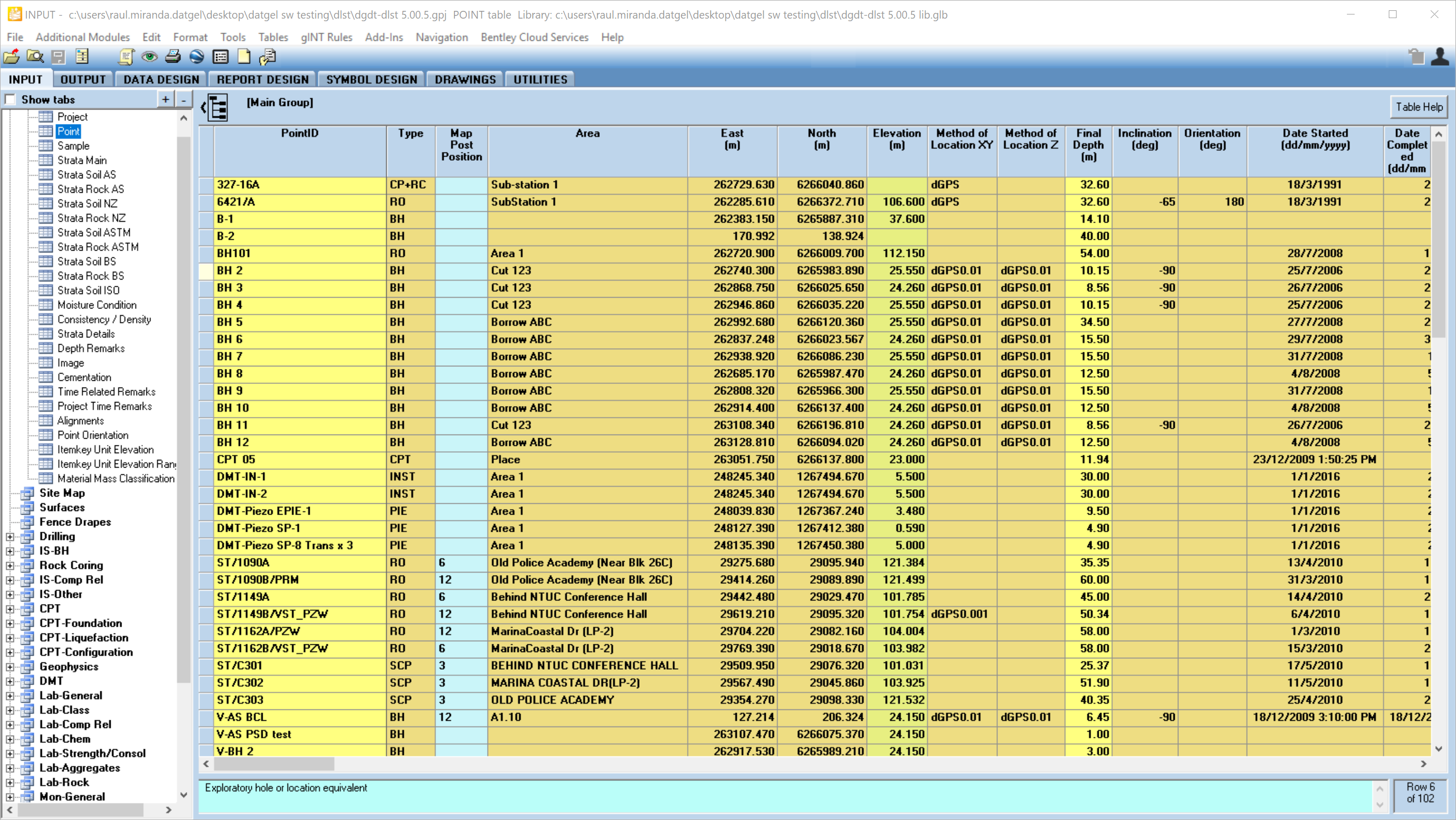
Main Group | Point table stores the general information related to the locations (Hole depth, coordinates, elevation, etc). Each row is a test location, such as a borehole or test pit.
Calculations
The Datgel DGD Tool includes some calculations, for example the SPT N value.
To test the calculations, go to the IS-BH | SPT table and select the borehole "BH 2" from the yellow drop-down list. You can see the values for the SPTs (depths, blows, penetrations, etc.).
Delete the existing green and pale yellow fields.
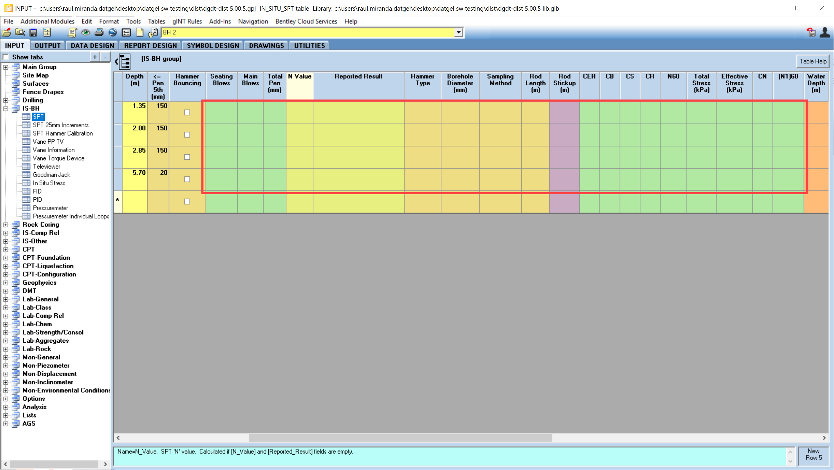
Click Save or Ctrl+S to initiate the calculations.

SPT.Seating_Blows, SPT.Main_Blows, SPT.Total_Penetration, SPT.N_Value, and SPT.Reported_Results are calculated and results are written to the fields.
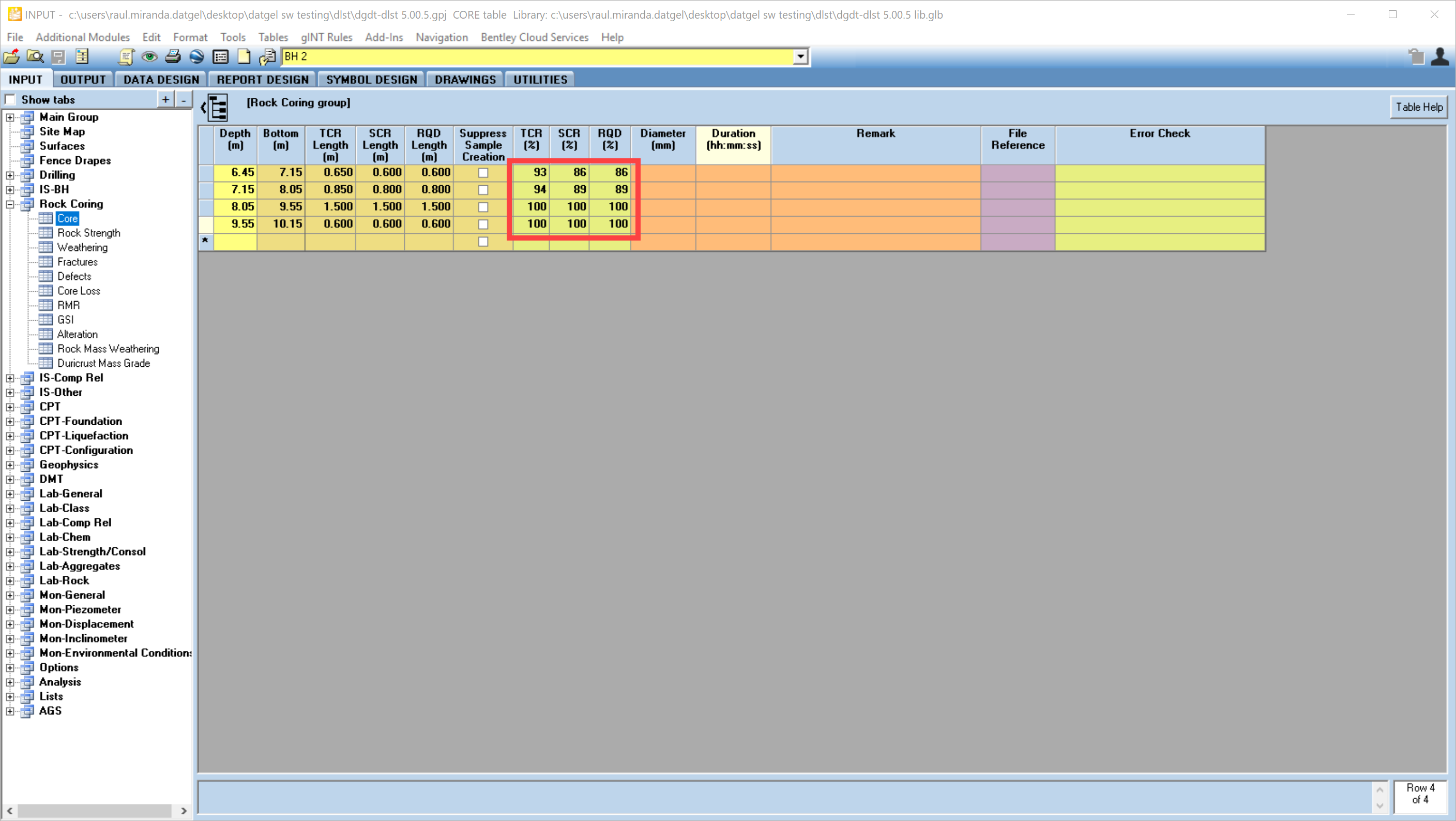
Another example of data calculations is in Rock Coring | Core table. You may delete and calculate the highlighted values to test the calculations.
Other data entry and calculations are described in the user guide.
Output a Log Report
The DGD Tool library contains more than 60 log reports.
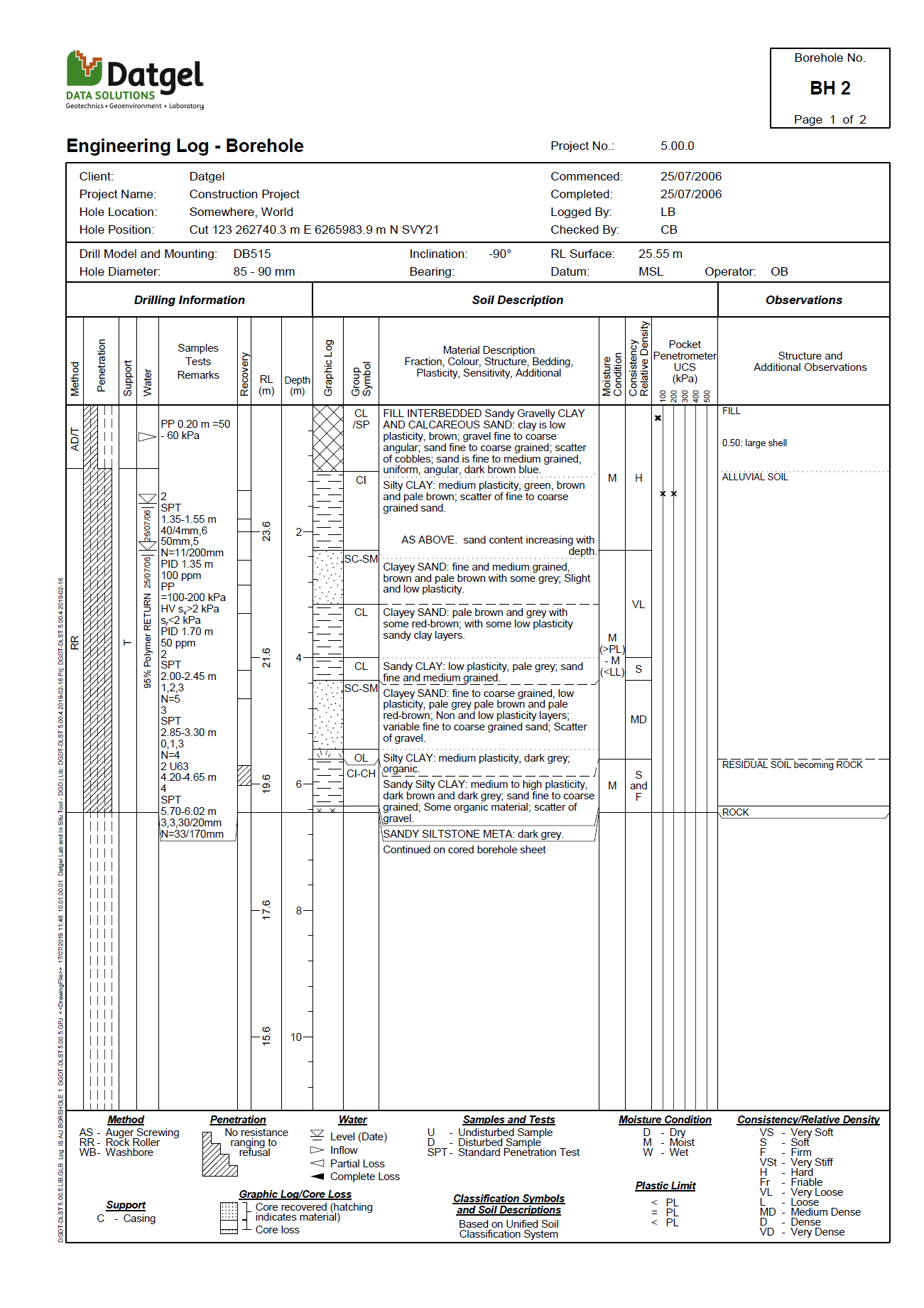
The following example explains how to output the PointID BH 2 to non cored (soil) and cored (rock) log reports to pdf.
- Go to OUTPUT | Logs
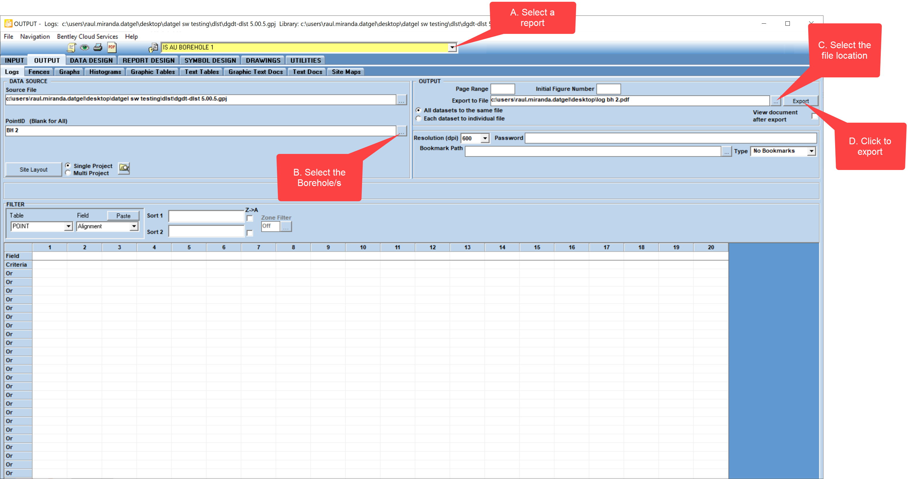
- Select the IS AU BOREHOLE 1 report from the yellow drop-down list.
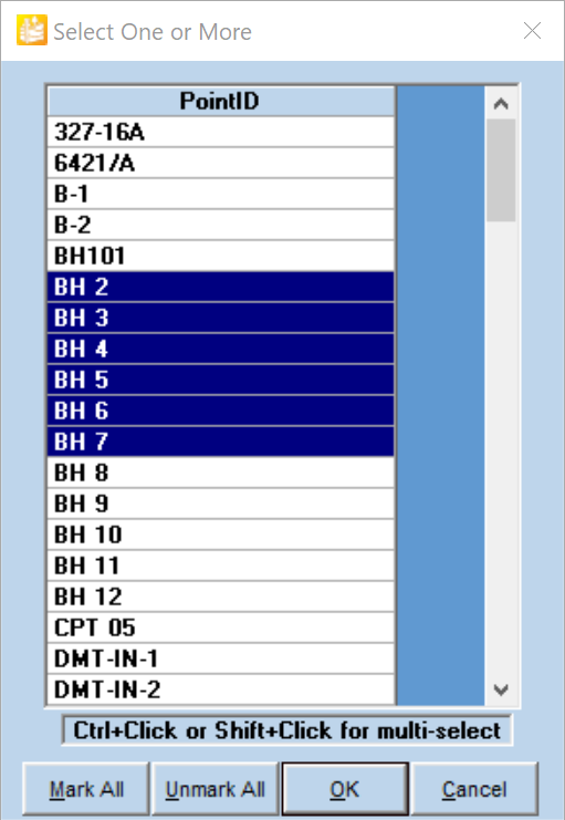
- Select the desired test from the KeySet picker: Click on the
 In this case BH 2.
- Click on the button and choose the name for new pdf document. Choose the location and click Save. Choose resolution 600 dpi.
- review the report. Close the pdf file.
- Alternatively, click the
 button to preview the report. You can review next page using the yellow drop-down list or press F6 button.
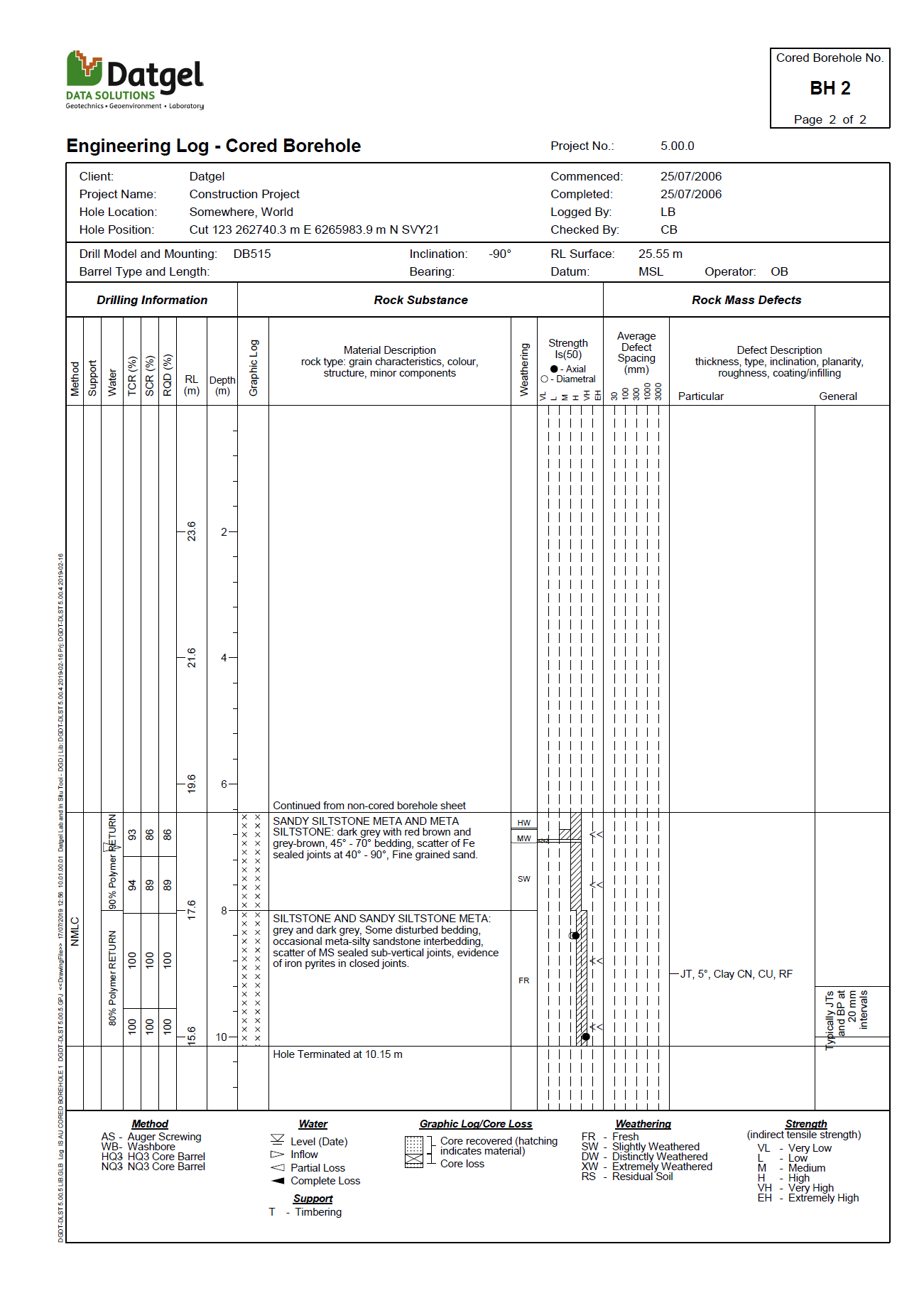
- Go to OUTPUT | Logs
- Select the IS AU CORED BOREHOLE 1 report form the yellow drop-down list.
- The KeySet picker shows the BH 2.
- The Export to File field shows the latest location. Choose the same file as the previous step.
- Check the box for View document after export.
- Review the pdf, it will have both reports.
- Alternatively, click the button to preview the report. You can review next page using the yellow drop-down list or press F6 button.
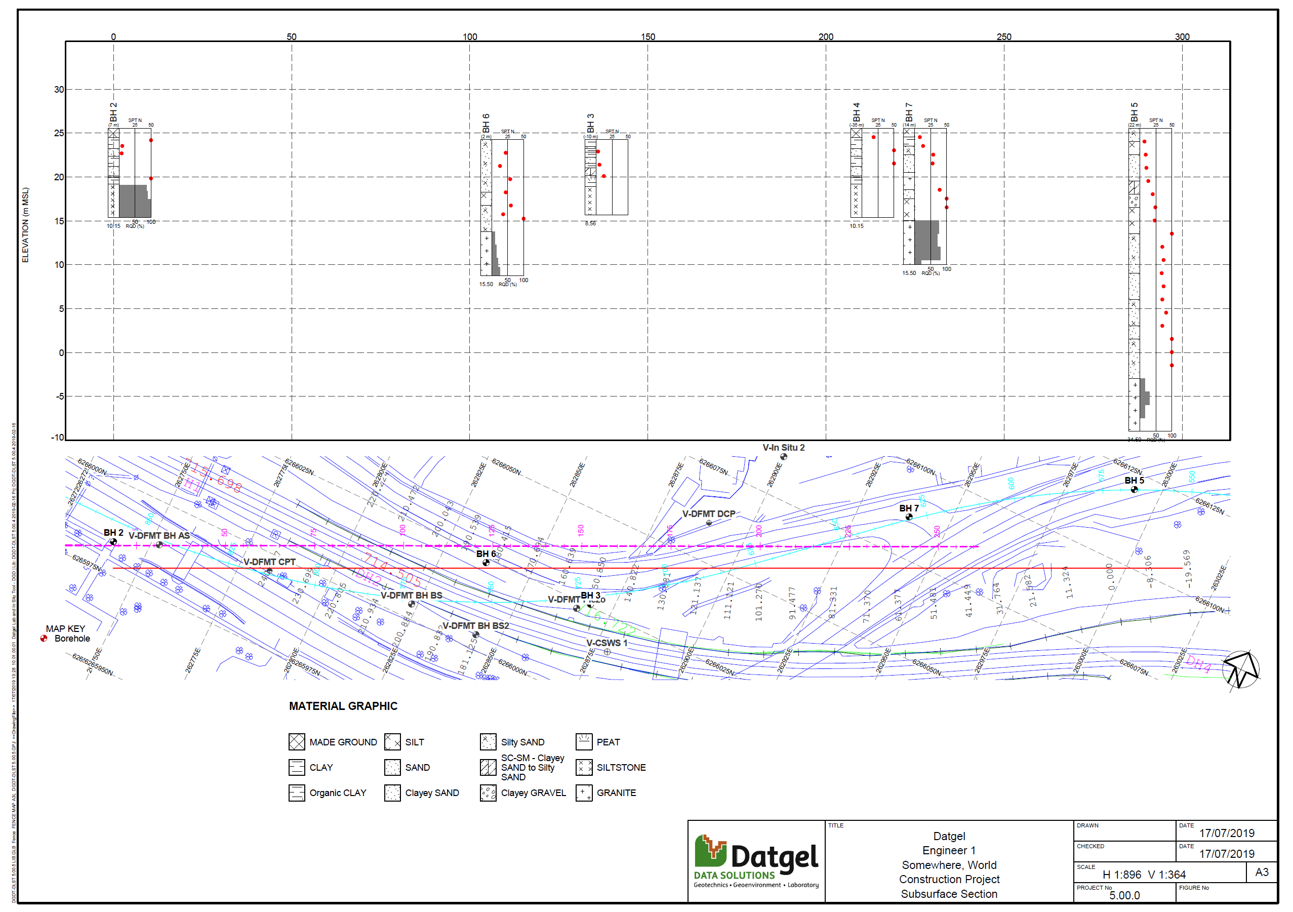
Output a Fence Diagram Report
The DGD Tool library contains 4 fence diagram reports.
- Go to OUTPUT | Fences.
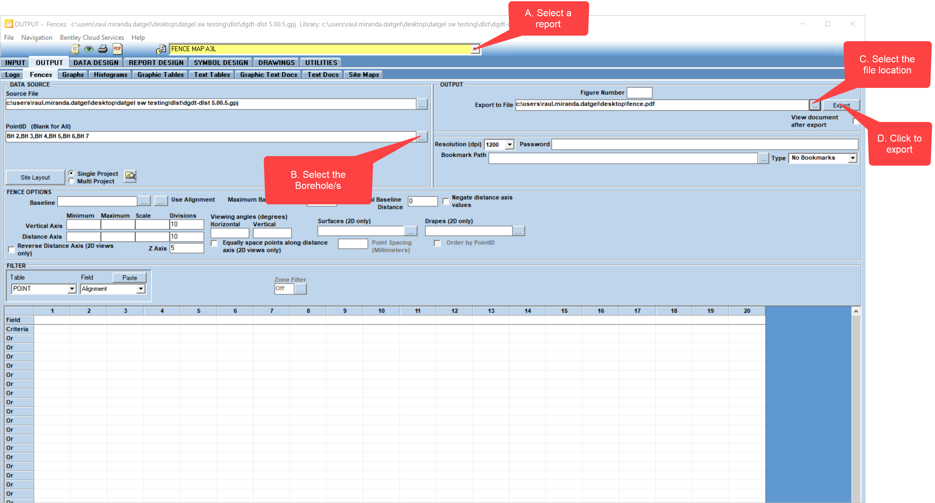
- Select the FENCE MAP A3L
- Select the desired test from the KeySet picker: Click on the
- Click on the button and choose the name for new pdf document. Choose the location and click Save. Check View document after export.
-
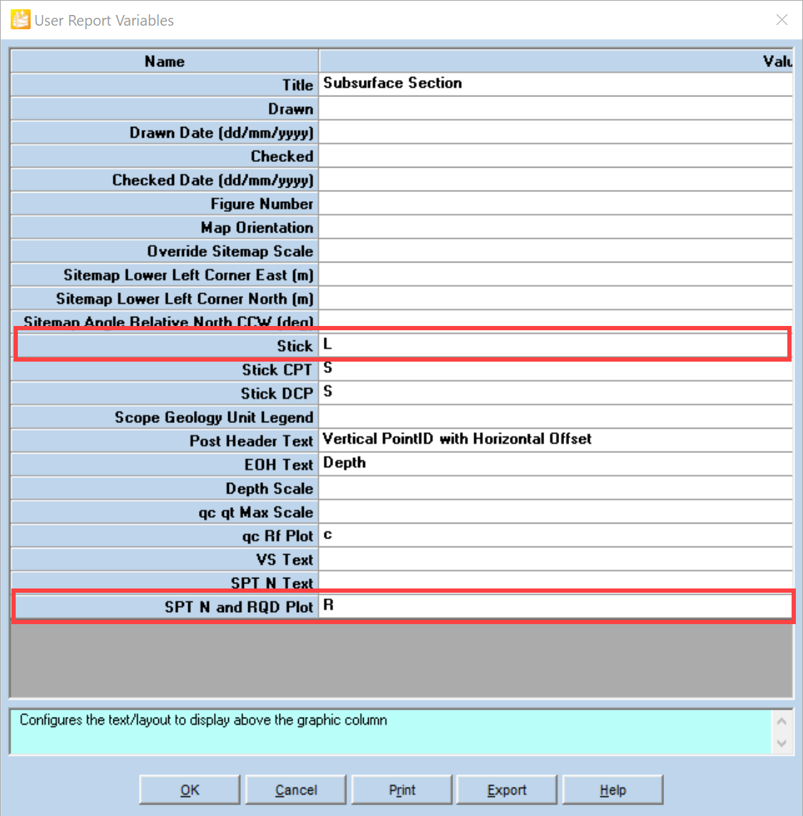
- Review the report.
- Alternatively, click the button to preview the report.