gINT Civil Tools Tutorial
Overview
This tutorial explains everyday tasks you may do in gINT Civil Tools (GCT), such as create a 2D map, create a 3D visualisation of gINT data, generate a terrain surface, and export to 3D PDF. We will not delve into all functionality. To gain more knowledge it is recommend you read the gINT Civil Tools Help and do a MicroStation training course.
What is gINT Civil Tools?
gINT Civil Tools is a power product (standalone application based on the MicroStation platform) that is delivered with gINT Pro and Pro Plus – it uses a gINT Pro or gINT Pro Plus license. It allows gINT users to load gINT data in 2D models (mapping workflow for drilling plan creation and preliminary studies), as well as in 3D for subsurface interpretation and BIM workflows.
gINT Civil Tools can connect to the gINT database (Access or SQL Server) to query, display in plan, display in 3D and display in a Civil profile any borehole from the gINT database. Additionally, you can create a MicroStation terrain model representation from a selection of or all points in your project for a given type of lithology. A smoother surface may also be generated by using an interpolation algorithm that generates a smoother and more attractive terrain model.
For tutorial videos and webinars please refer to:
- https://communities.bentley.com/products/geotechnical1/w/wiki/41382/gint-civil-tools
- http://learn.bentley.com/app/Public/ViewLearningPathDetails?lpId=111465
- 2017-12 (December) gINT SIG - Site Analysis using gINT Civil Tools
- 2017-07 (July) gINT SIG - gINT Civil Tools Essential for Subsurface Evaluation
gINT Civil Tools Licensing
The important thing to note about licensing is you must install and use the gINT Civil Tools product level that corresponds to your licensed gINT product level.
- gINT Logs - doesn't have a license for gINT Civil Tools
- gINT Professional - use gINT Civil Tools Professional Plus
- gINT Professional Plus - use gINT Civil Tools Professional Plus
Up until 2020, two version were published, GCT Pro and GCT Pro Plus. Subsequently only GCT Pro Plus has been published and this is used with both gINT Pro and gINT Pro Plus.
When you have gINT Civil Tools open it is using a gINT License. Having both gINT and gINT Civil Tools open at the same time on the same PC counts as one license use.
If you don't heed this you will get Quarterly Term License invoices for your use of the wrong gINT Civil Tools product level.
WorkSpace and WorkSet
A Workspace is a collection of projects, standards, and other related resources. You may have a Workspace for each client which includes the clients CAD standard files. A WorkSet is a like a project in gINT. Each Workspace in MicroStation CONNECT will have its own set of Worksets. Once you select a Workspace the Worksets for that Workspace will be available for selection in the drop-down list.
- Open gINT Civil Tools
- Make a WorkSpace named DGDTool, set root folder: C:\Datgel Training\
- Make a WorkSet named ABC
- Using File Explorer:
- Copy folder
C:\Datgel Training\Auxiliary Files\StandardstoC:\Datgel Training\DGDTool\WorkSets\ABC\
or - Copy
C:\ProgramData\Bentley\gINTCivilToolsProPlus CONNECT\Configuration\WorkSpaces\Example\WorkSets\IHL\Standards\Cell\Example_cells.celtoC:\Datgel Training\DGDTool\WorkSets\ABC\Standards\Cell\
- Copy folder
General
Most dialogs do not have an OK button. To make the action take place you need to click (normal left click) in the view.
If you want to clear data and re-query, first Ctrl+A and press Delete.
Display Explorer, Layers and Properties. Dock them on right, like in screen shot.
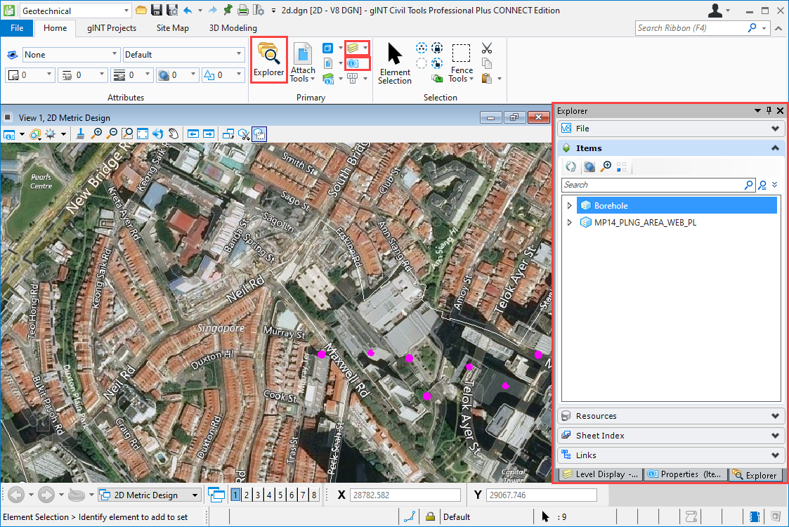
2D Map
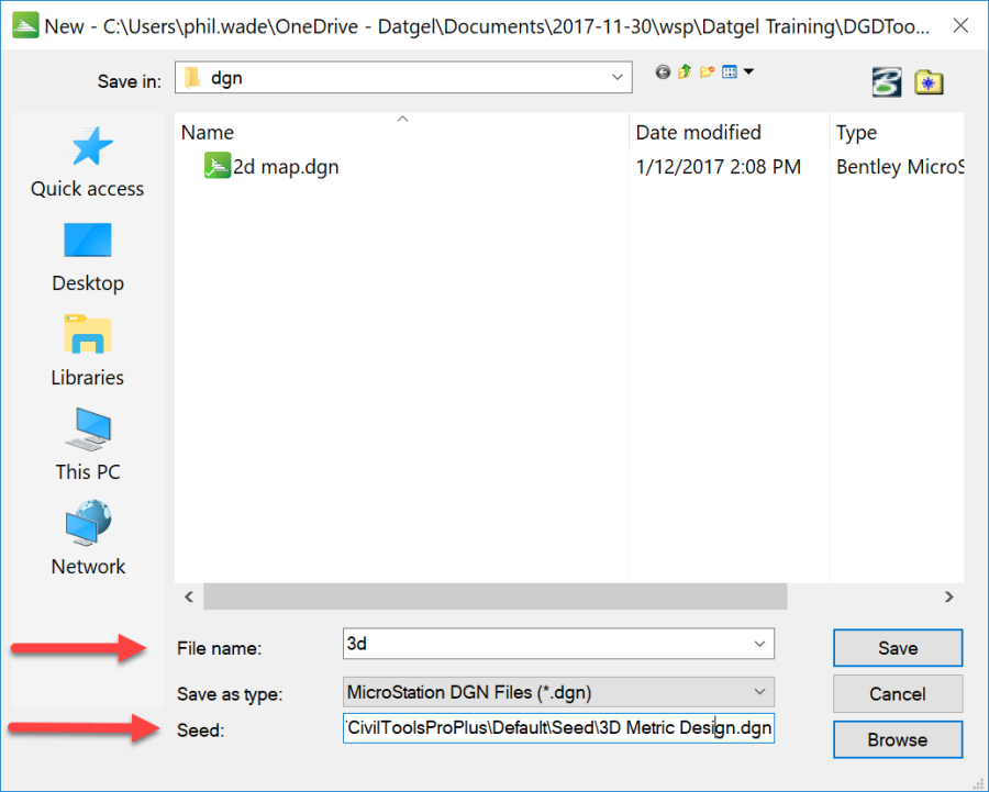
- Make a new drawing named
2D.dgn, use seed2D Metric Design.dgn - Select the Geotechnical workflow (lookup list in top left of screen)
- Select Site Map > Coordinate System, click
 and set Library\Projected\Asia\Singapore\SVY21, click OK
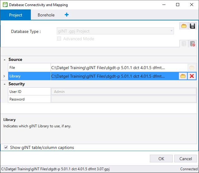
 - Select gINT Projects > Database Connectivity. Set:
- Database Type: gINT .gpj Project. If this is not in the list, see this .
- File: "C:\Datgel Training\gINT Files\dgdt-p 5.01.1 dct 4.01.5 dfmt 3.07.gpj"
- Library: "C:\Datgel Training\gINT Files\dgdt-p 5.01.1 dct 4.01.5 dfmt 3.07 lib trial.glb"
- Borehole Representation: PointType07
- Properties - load all fields from POINT
- Symbology: set as in screen shot. For Properties, add all by clicking the double green + icon.
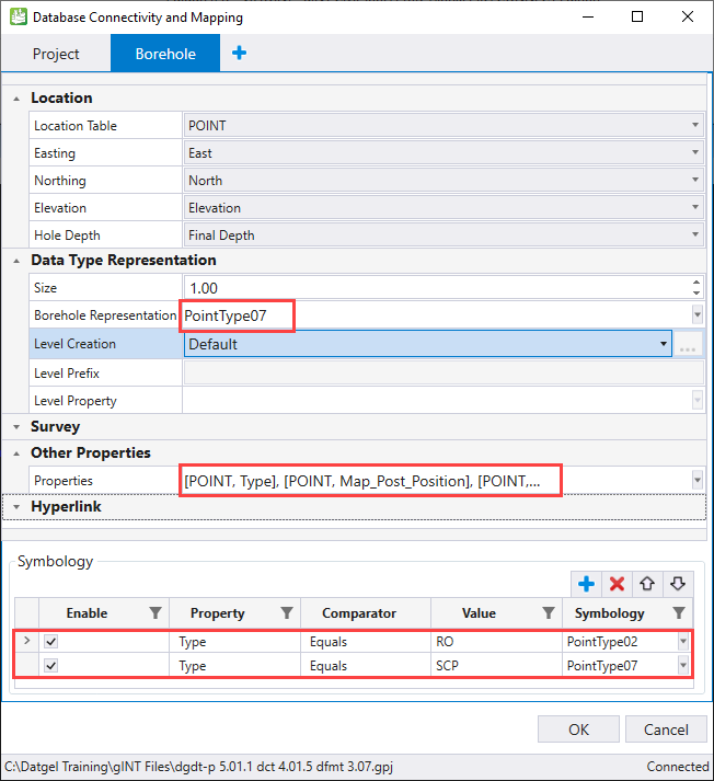
- Click OK
- Select Geotechnical > gINT Projects > Query, select rows with Name starting with ST, and click OK.
- Click on Fit View
 , and you should see the location in the map area.
 - File > Import > Common File Types > Shape File, select C:\Datgel Training\Auxiliary Files\MP14_PLNG_AREA_WEB_PL.shp
- Add Bing Maps:
- Select Geotechnical > Site Map, in Raster area, click on the icon
 in bottom right of ribbon section to open the Raster Manager
 - Attach Bing Maps
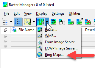
- Under Bing Map Layers select Aerials with labels. You can also change this later.
- Select Geotechnical > Site Map, in Raster area, click on the icon
- Using Explorer, zoom to Boreholes
- Label Boreholes using Geotechnical > gINT Projects > Annotate Points
 , set the option, and the left click in map area.
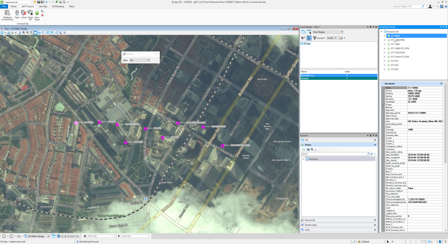
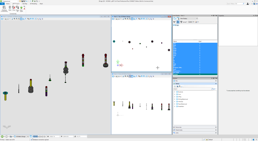
3D visualisation
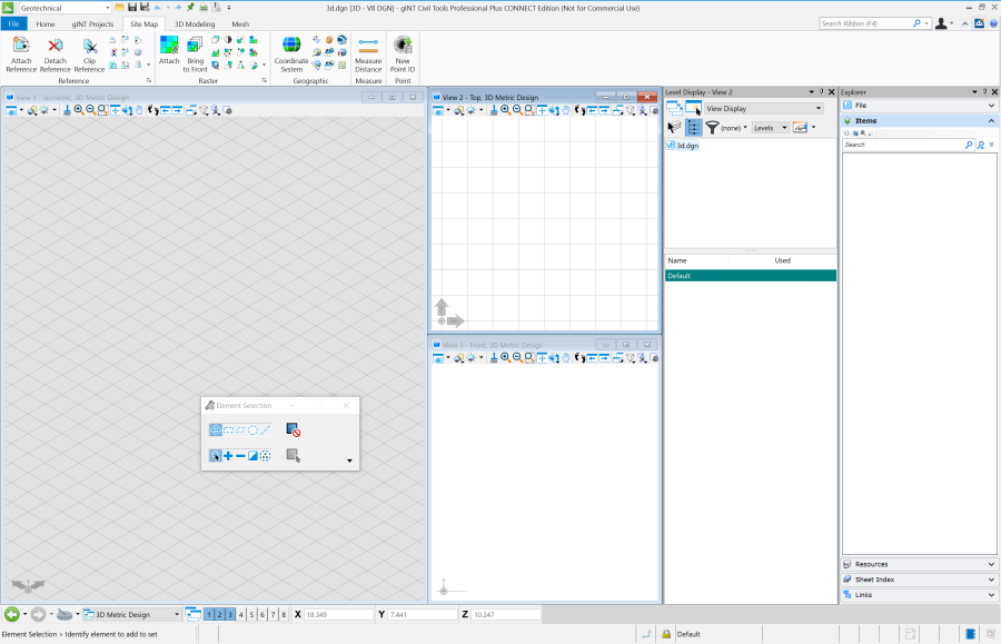
- Make a 3d drawing, using Seed: 3d Metric Design.dgn
- Enable Level Display, Explorer and Properties windows
- Select Geotechnical > gINT Projects > Database Connectivity
- Browse to C:\Datgel Training\gINT Files\dgdt-p #.## gct 3D ##.xml
- Browse to project and library
- Review the tabs in the Database Connectivity and Mapping form.
- Note how on StrataMain, we can set the Cylinder size
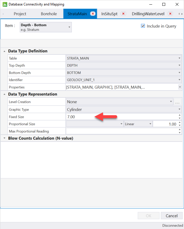
- There is an option on Depth-Bottom to calculate an N-Value, but the DGDT program does this, and the results are stored in the database so we don't need it.
- Make a new tab
- If Defects exist, first delete it
- Named Defects, Item = Depth Only
- On Project tab, uncheck Show gINT table/column captions
- Set the properties as in the screen shot
- For the property named Properties, click on the drop down arrow, then click on
 to add all fields
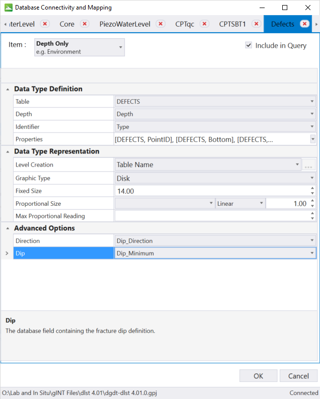
- Note how on StrataMain, we can set the Cylinder size
- Click OK
- Select Geotechnical > gINT Projects > Query, select rows with Name starting with ST and OK. Wait a while.
- In each view click on Fit View

Level manager
Launch the Level Manager, Geotechnical | Home > Primary > ![]() . Note
. Note
- the Boreholes_Decoration level
- You can set colours here
- You can import and export level configurations from a dgnlib, or link it using Configuration Variable MS_DGNLIBLIST
Annotate Item Types
Show Descriptions using Annotate Item Types. Geotechnical | gINT Projects > Annotate Item Types
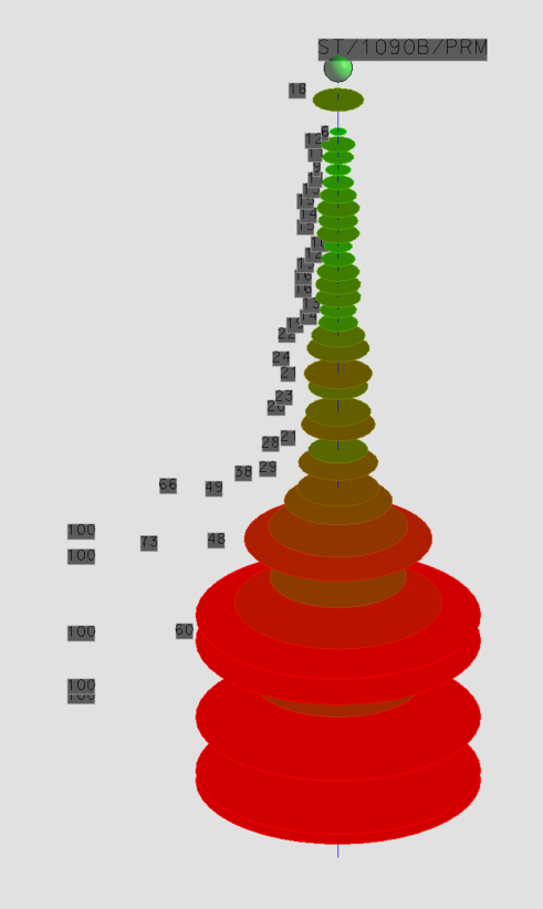
Colour ramp on objects
Colour ramp on objects, using display style, such as discs of SPT N Value
- Open the Display Styles dialog
- Copy the existing style currently in use
- Make a Display Rule and use the Generate option to make a color ramp based on InSituSpt N Value.
- Back in Display Styles, select the Rule from the combo box
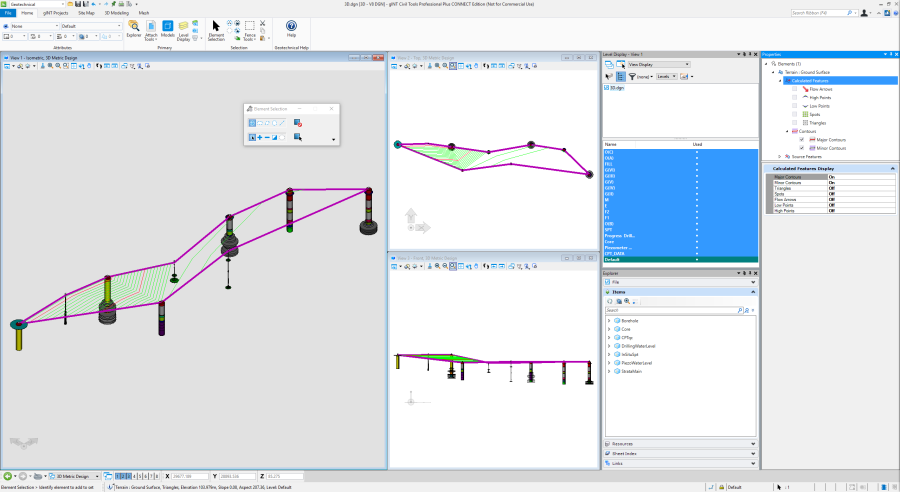
Make surface for ground
- Select Geotechnical > 3D Modeling > Create Existing Ground
- Check Use All Boreholes
- Set Terrain Name to Ground Surface
- Then click somewhere in the View 1, this is like clicking OK and the Terrain is made
- Select the Terrain element in the view, and using the Properties window you can control what is displayed
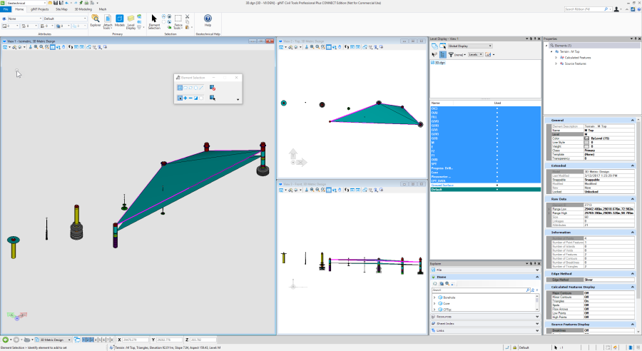
Isolate one geology unit
- In the Explorer window, expand StrataMain
- Right click on M, and select Isolate
- You can then select Clear Isolate
Make Terrain for a geologic unit layer
- Select Geotechnical > 3D Modeling > Create Terrain
- Set the following:
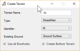
- Click somewhere in the View 1, this is like clicking OK and the Terrain is made
- Edit layers:
- Changed the colour of the M layer, done in the Level Manger
- Make a new level called Ground Surface, then in the entity properties set the Ground Surface terrain to then new layer and turned it off in the Level Display
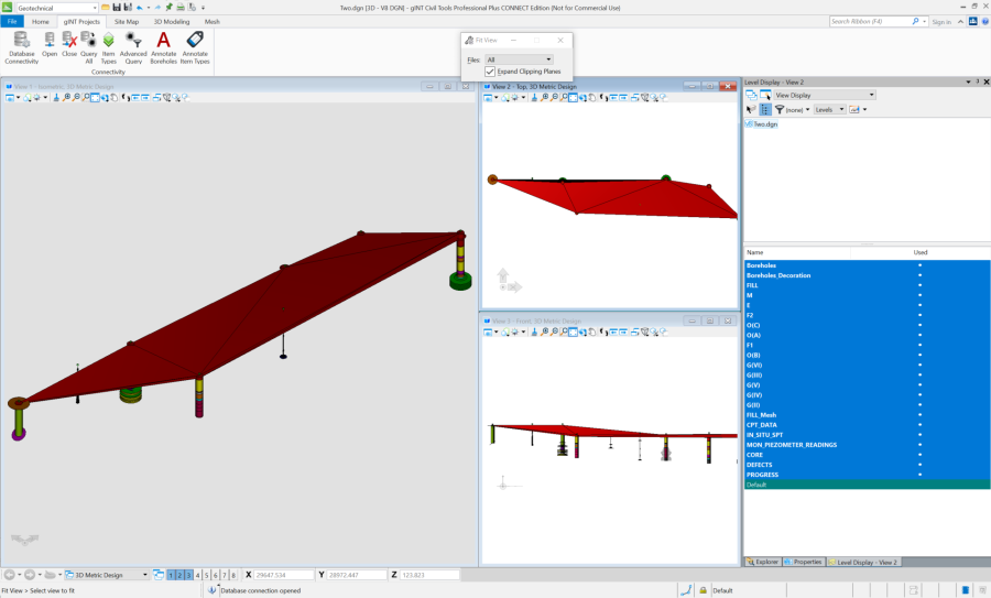
Create a Mesh for a geologic unit layer
A mesh is a solid 3D object, where a Terrain is a surface
- Select Geotechnical > 3D Modeling > Create Mesh
- Set the following:
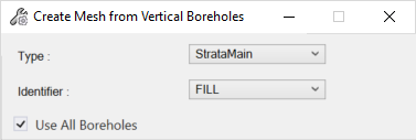
- Click somewhere in the View 1, this is like clicking OK and the mesh is made
- This is on a new layer FILL_Mesh
Cross Sections
- Place Smart Line
- Create Cross Section
- Create Fence Diagram
- Add Terrain to a Cross section, and edit line either by dragging a node or to extend the line use Drawings | Modify > Extend Line

Export to LandXML
Export to LandXML, and import into gINT.
Export to 3D PDF
File > Print > Print to PDF
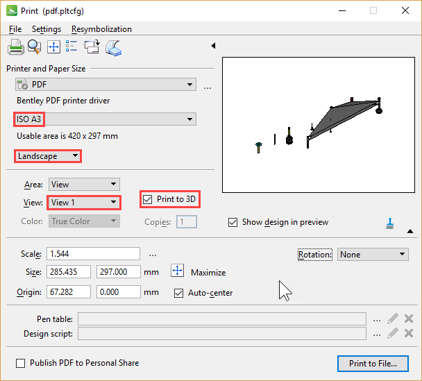
View file using Acrobat. Note Nitro Pro doesn't support 3D.