Foundation Correlations
Overview
Foundation related correlations are defined in this section.
Pile Axial Capacity
Soil Description
The soil description in Pile_Axial_Capacity_Soil_Description_1 is defined based on the cone resistance, q_c , according to table below:
| Nature of soil | q_c |
|---|---|
| Soft clay and mud | < 1 |
| Moderately compact clay | 1 to 5 |
| Silt and loose sand | ≤ 5 |
| Compact to stiff clay and compact silt | > 5 |
| Soft chalk | ≤ 5 |
| Moderately compact sand and gravel | 5 to 12 |
| Weathered to fragmented chalk | > 5 |
| Compact to very compact sand and gravel | > 12 |
CPT in geotechnical practice, pp. 152-154
Unit End Bearing
The unit end bearing, q_p, in Pile_Axial_Capacity_Unit_End_Bearing_1 based on the method by Bustamante and Gianeselli (1982) is defined as:
| q_p=k_c*q_{ca} |
The method also is known as LCPC method
CPT in geotechnical practice, pp. 152-154
Where:
k_c is read from table below (CPT in geotechnical practice, p152, Table 6.4) based on the cone resistance and soil type.
q_{ca} is the equivalent average cone resistance at the base of the pile, is the mean q_c
value measured along two fixed distances a (a=1.5 D, where D is the pile diameter) above (-a) and below (+a) the pile tip. The q_{c} values are bounded to a maximum of 1.3 q_c' along the length –a to +a, and the minimum of 0.7 q_c' along the –a, in which q_c' is the mean value of q_c between –a and +a.
| Nature of soil | q_c
| Factor k_c | |
|---|---|---|---|
| Group I | Group II | ||
| Soft clay and mud | < 1 | 0.4 | 0.5 |
| Moderately compact clay | 1 to 5 | 0.35 | 0.45 |
| Silt and loose sand | ≤ 5 | 0.4 | 0.5 |
| Compact to stiff clay and compact silt | > 5 | 0.45 | 0.55 |
| Soft chalk | ≤ 5 | 0.2 | 0.3 |
| Moderately compact sand and gravel | 5 to 12 | 0.4 | 0.5 |
| Weathered to fragmented chalk | > 5 | 0.2 | 0.4 |
| Compact to very compact sand and gravel | > 12 | 0.3 | 0.4 |
- Group I: plain bored piles, mud bored piles, micro piles (grouted under low pressure), cased bored piles, hollow auger bored piles, piers, barrettes.
- Group II: cast screwed piles, driven precast piles, prestress tubular piles, driven cast piles, jacked metal piles, micropiles (small diameter piles grouted under high pressure with diameter < 250 mm), driven grouted piles (low pressure grouting), driven metal piles, driven rammed piles, jacket concrete piles, high pressure grouted piles of large diameter.
Unit Side Friction
The unit side friction, f_p, in Pile_Axial_Capacity_Unit_Side_Friction_1 based on the method by Bustamante and Gianeselli (1982) is defined as:
| f_p=q_c/\alpha_{LCPC} |
CPT in geotechnical practice, pp. 152-154
Where:
\alpha_{LCPC} and maximum limit of fp are given in the following table (CPT in geotechnical practice, table 6.5).
Nature of soil | q_c
| Coefficient \alpha | Maximum limit of f_p (MPa) | ||||||||
|---|---|---|---|---|---|---|---|---|---|---|---|
| I | II | I | II | III | |||||||
| A | B | A | B | A | B | A | B | A | B | ||
| Soft clay and mud | < 1 | 30 | 90 | 90 | 30 | 0.015 | 0.015 | 0.015 | 0.015 | 0.035 | |
| Moderately compact clay | 1 to 5 | 40 | 80 | 40 | 80 | 0.035 (0.08) | 0.035 (0.08) | 0.035 (0.08) | 0.035 | 0.08 | ≥ 0.12 |
| Silt and loose sand | ≤ 5 | 60 | 150 | 60 | 120 | 0.035 | 0.035 | 0.035 | 0.035 | 0.08 | - |
| Compact to stiff clay and compact silt | > 5 | 60 | 120 | 60 | 120 | 0.035 (0.08) | 0.035 (0.08) | 0.035 (0.08) | 0.035 | 0.08 | ≥ 0.20 |
| Soft chalk | ≤ 5 | 100 | 120 | 100 | 120 | 0.035 | 0.035 | 0.035 | 0.035 | 0.08 | - |
| Moderately compact sand and gravel | 5 to 12 | 100 | 200 | 100 | 200 | 0.08 (0.12) | 0.035 (0.08) | 0.08 (0.12) | 0.08 | 0.12 | ≥ 0.20 |
| Weathered to fragmented chalk | > 5 | 60 | 80 | 60 | 80 | 0.12 (0.15) | 0.08 (0.12) | 0.12 (0.15) | 0.12 | 0.15 | ≥ 0.20 |
| Compact to very compact sand and gravel | > 12 | 150 | 300 | 150 | 200 | 0.12 (0.15) | 0.08 (0.12) | 0.12 (0.15) | 0.12 | 0.15 | ≥ 0.20 |
Note: maximum limit unit skin friction, f_p: bracket values apply to careful execution and minimum disturbance of soil due to construction.
Category
- IA: plain bored piles, mud bored piles, hollow auger bored piles, micro piles (grouted under low pressure), cast screwed piles, piers, barretes.
- IB: cased bored piles, driven cast piles (concrete or metal shaft).
- IIA: driven precast piles, prestress tubular piles, jacket concrete piles.
- IIB: driven metal piles, jacked metal piles
- IIIA: driven grouted piles, driven rammed piles.
- IIIB: high pressure grouted piles of large diameter >250mm, micropiles (grouted under high pressure).
End Bearing Capacity
The end bearing capacity, Q_b, in Pile_Axial_Capacity_End_Bearing_1 is calculated as the product between the pile end area, A_p, and the unit end bearing, q_p:
| Q_b=q_p \cdot A_p |
CPT in geotechnical practice, pp. 152-154
Side Friction Capacity
The friction capacity, Q_f, in Pile_Axial_Capacity_Side_Friction_1 is the product between the outer pile shaft area, A_s, by the the unit side friction, f_p, as:
| Q_f= \sum f_p \cdot A_s |
CPT in geotechnical practice, pp. 152-154
Ultimate Axial Capacity
The ultimate pile axial capacity, Q_{ult} , in Pile_Axial_Capacity_Ultimate_1 consists of two components: side friction capacity, Q_f, and end bearing capacity, Q_b, as:
| Q_{ult}=Q_f+Q_b |
CPT in geotechnical practice, pp. 152-154
Allowable End Bearing Capacity
The allowable end bearing capacity, Q_{ba}, in Pile_Axial_Allowable_End_Bearing_1 is calculated as pile end bearing capacity divided by factor of safety:
| Q_{ba}= \frac{Qb}{FS} |
CPT in geotechnical practice, p. 155
Where:
FS is read from Pile_End_Bearing_Factor_of_Safety in foundation project parameters table. Default value for factor of safety is 3.
Allowable Side Friction Capacity
The allowable side friction capacity, Q_{fa}, in Pile_Axial_Allowable_Side_Friction_1 is calculated as pile side friction capacity divided by factor of safety:
| Q_{fa}= \frac{Q_f} {FS} |
CPT in geotechnical practice, pp. 152-154
Where:
FS is read from Pile_Side_Friction_Factor_of_Safety in foundation project parameters table. Default value for factor of safety is 2.
Allowable Axial Capacity
The pile axial allowable capacity, Q_a , in Pile_Axial_Allowable_Capacity__1 consists of two components: allowable side friction capacity, Q_{fa}, and allowable end bearing capacity, Q_{ba}, as:
| Q_a=Q_{fa}+Q_{ba} |
CPT in geotechnical practice, p. 155
Bulk Unit Weight (Foundation)
Bulk Unit Weight may be defined in two locations and are used in the order listed:
- CPT_POINT_MATERIAL_PROPERTIES table (Point Parameters – Bottom half). This allows you to enter a depth profile. If a depth range is missing a value, then the CPT_PROJECT_PARAMETERS table is used.
- CPT_PROJECT_PARAMETERS table. A saturated and unsaturated bulk unit weight must be defined, the former is applied bellow the water table and the later above the water table. Water table is from either design groundwater table for foundation from CPT_FOUNDATION_PROJECT_PARAMETERS / CPT_FOUNDATION_POINT_PARAMETERS or ground water depth from CPT_POINT_PARAMETERS/ CPT_PROJECT_PARAMETERS.
In-Situ Pore Pressure (Foundation)
In-Situ Pore Pressure may be defined in two methods and are used in the order listed:
- CPT_POINT_MATERIAL_PROPERTIES table (Point Parameters – Bottom half). This allows you to enter a depth profile.
- The in-situ pore pressure for foundation is calculated based on the position of design groundwater table for foundation from CPT_FOUNDATION_PROJECT_PARAMETERS or CPT_ FOUNDATION _POINT_PARAMETERS.
Total Stress (Foundation)
The total stress for foundation is calculated using bulk unit weight (foundation). The total stress (foundation) is used for shallow foundation settlement.
Effective Stress (Foundation)
The effective stress for foundation is calculated from total stress (foundation) and pore pressure (foundation). The effective stress (foundation) is used for calculation of shallow foundation settlement.
Young's Modulus Alpha, α
The alpha value in Alpha based on the value/method selected in Alpha on CPT_FOUNDATION_POINT_PARAMETERS and/or CPT_FOUNDATION_PROJECT_PARAMETERS tables, is taken from Alpha field, or calculated from q_c
, effective stress, reduction factor and degree of loading (q/q_{ult}) in Degree_of_Loading as per suggested by Robertson (1991).
CPT in Geotechnical Practice, Figure 6.13, p. 160
Young's Modulus, E
The Young's modulus in Young_Modulus based on the method selected in Young_Modulus_Method is calculated either from Alpha (Alpha method, E= \alpha q_c) or from shear wave velocity as
| E=G \cdot 2 \cdot(1+v)\\ \ \\ G= \rho V_s^2 |
Where V_s s is the shear wave velocity in Shear_Wave_Velocity_Extrapolated on CPT DATA table.
Shallow Foundation Settlement
Square Shallow Foundation Settlement 1
Foundation settlement method 1 for shallow foundations is based on the strain influence approach, method by Schmertmann (1978) for square footing (L/B=1). This is applicable to coarse soils.
| s=C_1C_2 \Delta p \sum_{1}^{n}\frac{I_z}{C_3E} \Delta z\\ \ \\ C_1=1-0.5\frac{\sigma'_1}{\Delta p} \\ \ \\ C_2=1-0.2log_{10}10t\\ \ \\ C_3=1.25 |
CPT in Geotechnical Practice, pp. 158-160
Where:
\Delta p is net foundation pressure which is foundation pressure (q) in Foundation_Pressure on CPT_FOUNDATION_POINT_PARAMETERS and/or CPT_FOUNDATION_PROJECT_PARAMETERS tables, minus effective overburden pressure at the foundation level, \sigma'_{v0,1}
I_z is strain influence factor, linearly increases from 0.1 at foundation level to peak value of I_{zp}=0.5+0.1 \left ( \frac {\Delta p}{\sigma'_{vo,z}} \right ) ^{0.5} at depth of B/2 below foundation level, and reduces to zero at depth of 2B below foundation level.
\Delta z is thickness of sub-layer
E is the Young's modulus and stored in Young_Modulus on CPT_DATA_FOUNDATION
\sigma'_{v0,z} is the effective overburden pressure at the level of peak I_z (see figure below). Effective stresses are calculated using the design groundwater depth on CPT_FOUNDATION_POINT_PARAMETERS and/or CPT_FOUNDATION_PROJECT_PARAMETERS 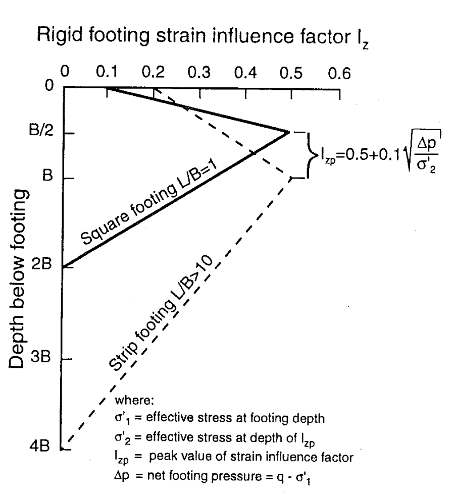
Strip Shallow Foundation Settlement 2
Foundation settlement method 2 for shallow foundations based on the strain influence approach, method by Schmertmann (1978) for strip footing (L/B >10). This is applicable to coarse soils.
| s=C_1C_2 \Delta p \sum_{1}^{n}\frac{I_z}{C_3E} \Delta z\\ \ \\ C_1=1-0.5\frac{\sigma'_1}{\Delta p} \geq0.5 \\ \ \\ C_2=1-0.2log_{10}10t\\ \ \\ C_3=1.25 |
Where:
\Delta p is net foundation pressure which is foundation pressure (q) in Foundation_Pressure on CPT_FOUNDATION_POINT_PARAMETERS and/or CPT_FOUNDATION_PROJECT_PARAMETERS tables, minus effective overburden pressure at the foundation level, \sigma'_{v0,1}
I_z is strain influence factor, linearly increases from 0.2 at foundation level to peak value of I_{zp}=0.5+0.1 \left ( \frac {\Delta p}{\sigma'_{vo,z}} \right ) ^{0.5} at depth of B below foundation level, and reduces to zero at depth of 4B below foundation level.
\Delta z is thickness of sub-layer
E is the Young's modulus and stored in Young_Modulus on CPT_DATA_FOUNDATION
\sigma'_{v0,z}' is the effective overburden pressure at the level of peak I_z. Effective stresses are calculated using the design groundwater depth on CPT_FOUNDATION_POINT_PARAMETERS and/or CPT_FOUNDATION_PROJECT_PARAMETERS
Rectangular Shallow Foundation Settlement 3
Foundation settlement method 3 for shallow foundations based on the strain influence approach, method by Schmertmann (1978) for footing with 1 < L/B < 10 is interpolated between foundation settlement 1 and 2. This is applicable to coarse soils.